Low-resistance coreless unilateral permanent magnet synchronous linear motor

A permanent magnet synchronous linear, iron-free technology, applied in piezoelectric effect/electrostrictive or magnetostrictive motors, generators/motors, electromechanical devices, etc., can solve the problem of reducing the robustness of the system, and achieve Effects of improving robustness, reducing positive pressure, and suppressing thrust fluctuations

Active Publication Date: 2020-01-17
安徽同兴科技发展有限责任公司 +1
View PDF5 Cites 6 Cited by
  • Summary
  • Abstract
  • Description
  • Claims
  • Application Information

AI Technical Summary

Problems solved by technology

[0002] The breakthrough in the structure of the linear motor enables it to be directly driven linearly without other intermediate links, and has the characteristics of zero rotation of the feed system. When the linear motor performs linear motion under the action of an electromagnetic field, guide rails are needed to regulate and limit The travel route, so there is unavoidable sliding friction resistance, which is proportional to the positive pressure of the mover on the guide rail. The linear motor mover is used as a load unit. As the actual load increases, the thrust fluctuation will be much higher than the ideal experimental data. , while reducing the robustness of the system

Method used


Image

  • Low-resistance coreless unilateral permanent magnet synchronous linear motor
  • Low-resistance coreless unilateral permanent magnet synchronous linear motor
  • Low-resistance coreless unilateral permanent magnet synchronous linear motor

Examples


Embodiment Construction

[0009] In order to make the purpose, technical solutions and advantages of the embodiments of the present invention clearer, the technical solutions in the embodiments of the present invention will be clearly and completely described below in conjunction with the drawings in the embodiments of the present invention. Obviously, the described embodiments It is a part of embodiments of the present invention, but not all embodiments. Based on the embodiments of the present invention, all other embodiments obtained by persons of ordinary skill in the art without creative efforts fall within the protection scope of the present invention.

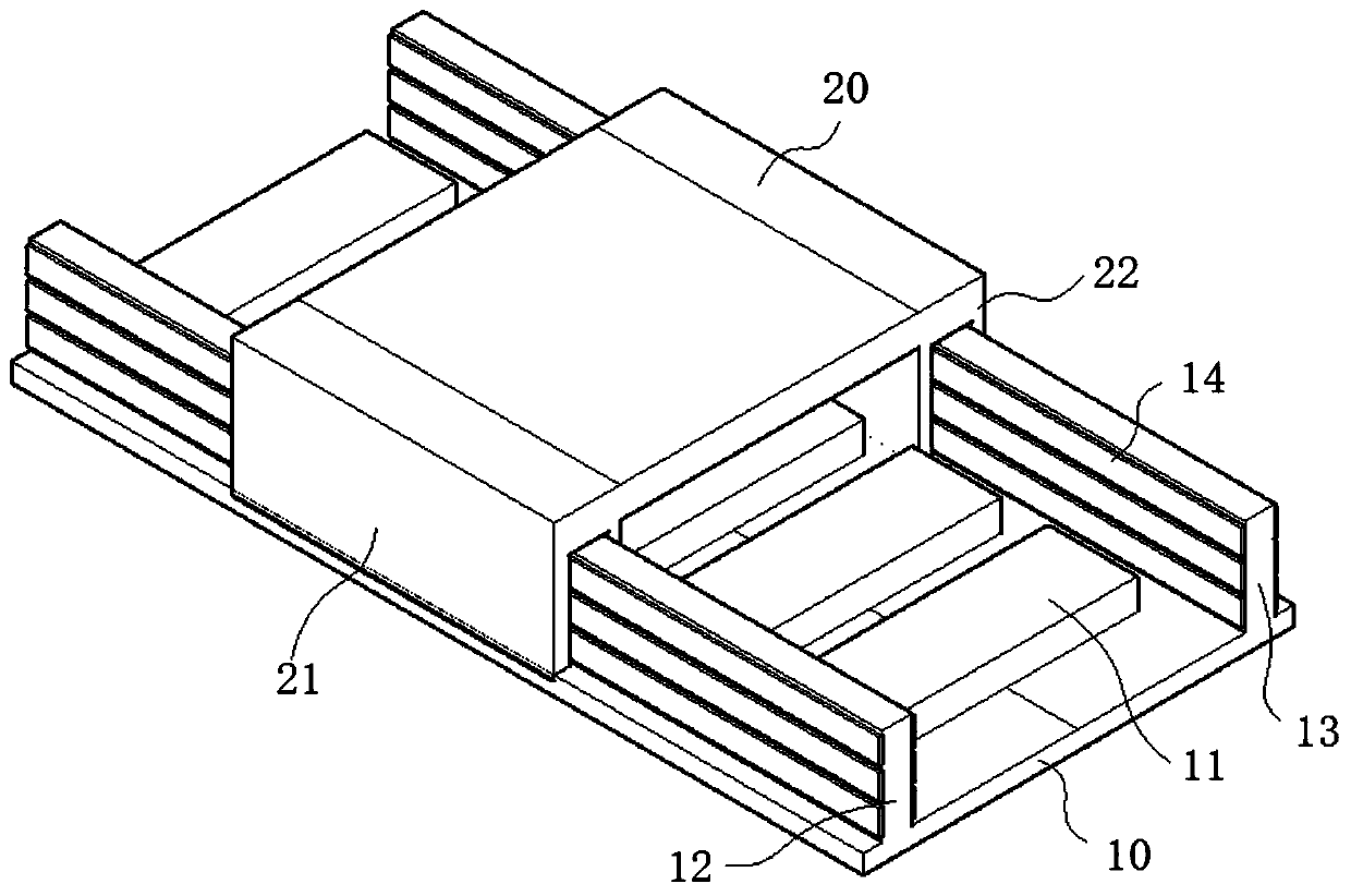
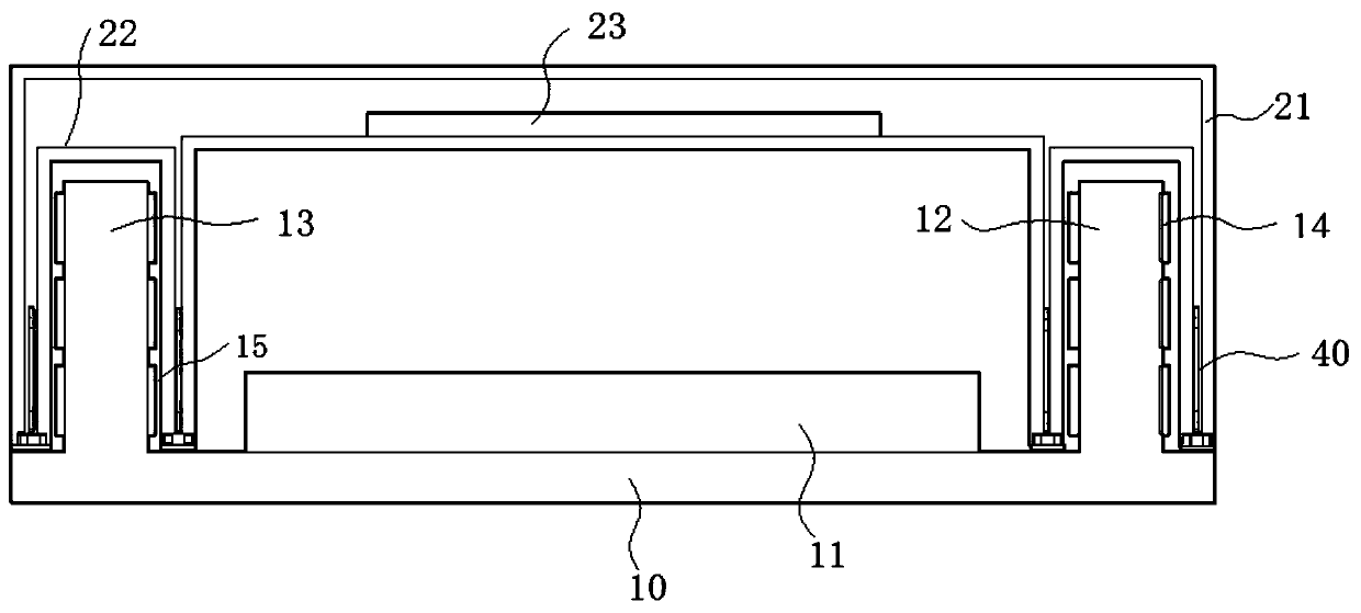
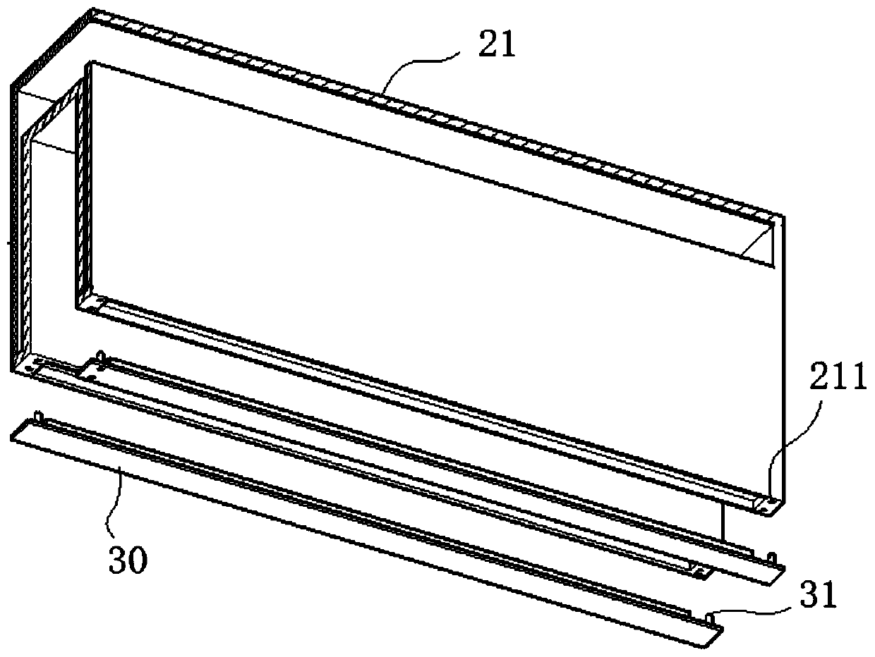
[0010] see Figure 1-3 As shown, a low-resistance coreless unilateral permanent magnet synchronous linear motor includes a linear guide rail 10 with permanent magnets 11 laid out at intervals along the axial direction, and a mover seat 20 that forms a sliding fit with the linear guide rail 10, and the mover seat The energized coil 23 is arranged ...


PUM


Abstract

The invention relates to the field of permanent-magnet linear motors, and discloses a low-resistance coreless unilateral permanent magnet synchronous linear motor that includes a linear guide rail, wherein permanent magnets are laid on the linear guide rail at intervals in the axial direction. The motor also comprises a mover seat that is in sliding fit with the linear guide rail; a first rail anda second rail are symmetrically arranged on the linear guide rail in parallel in the axial direction. A first guide groove and a second guide groove of which the groove walls are cavities are correspondingly formed in the mover seat; at least one long steel magnet is arranged on at least one axial side wall of each of the first rail and the second rail in the vertical direction; the groove bottoms of the first guide groove, the second guide groove and the long steel magnets on the same side are connected with piezoelectric ceramics; coils are arranged in adjacent groove wall cavities, and thecoils are connected with the piezoelectric ceramics through wires. The guide effect of the guide rail is reserved; when the mover seat bears load and is pressed, the positive voltage effect of piezoelectric ceramic is used for providing current for the coil, so upward lifting force is generated on the mover seat under cutting of a symmetric magnetic field of the long steel magnets, thrust fluctuation is restrained, and the robustness of an advancing system is improved.

Description

technical field [0001] The invention relates to the field of permanent magnet linear motors, in particular to a low-resistance iron-coreless single-side permanent magnet synchronous linear motor. Background technique [0002] The breakthrough in the structure of the linear motor enables it to be directly driven linearly without other intermediate links, and has the characteristics of zero rotation of the feed system. When the linear motor performs linear motion under the action of an electromagnetic field, guide rails are needed to regulate and limit The travel route, so there is unavoidable sliding friction resistance, which is proportional to the positive pressure of the mover on the guide rail. The linear motor mover is used as a load unit. As the actual load increases, the thrust fluctuation will be much higher than the ideal experimental data. , while reducing the robustness of the system. Contents of the invention [0003] Aiming at the deficiencies of the prior art...

Claims


Application Information

Patent Timeline
Patent Type & Authority Applications(China)
IPC IPC(8): H02K41/03H02N2/18
CPCH02K41/031H02N2/18
Inventor 罗群罗亮赵吉文
Owner 安徽同兴科技发展有限责任公司
Why Eureka
Try Eureka