

Piezoelectric inertia and piezoelectric worm-creep hybrid rotary driver
A rotary drive, hybrid technology, applied in the directions of generators/motors, piezoelectric effect/electrostrictive or magnetostrictive motors, electrical components, etc., can solve the problems of small driving force and slow driving speed, and achieve driving The effect of large stroke, large driving torque and fast driving speed
- Summary
- Abstract
- Description
- Claims
- Application Information
AI Technical Summary
Problems solved by technology
Method used
Image

Examples
Embodiment 1
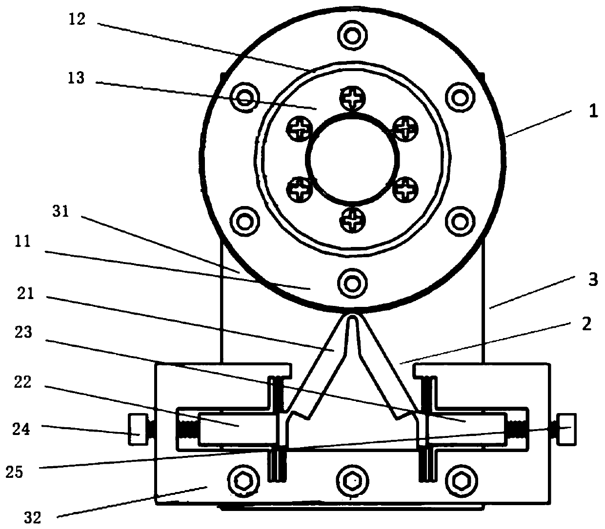
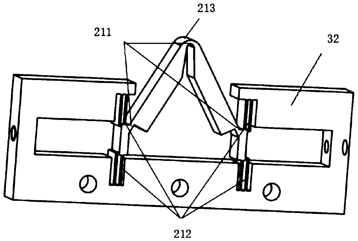
[0027] Such as figure 1 and figure 2 As shown, a piezoelectric inertial and piezoelectric worm hybrid rotary driver includes a bearing mechanism 1, a driving mechanism 2 and a fixing mechanism 3; wherein: the driving mechanism 2 includes a triangular flexible driving member 21, a first driver 22, The second driver 23, the first connecting member 24 and the second connecting member 25; wherein: the triangular flexible driving member 21 is fixedly connected with the first driver 22 and the second driver 23 respectively, and the first driver 22 and the second driver 23 are symmetrically arranged on the fixing mechanism 3 through the first connecting piece 24 and the second connecting piece 25 respectively; the bearing mechanism 1 is fixed through the fixing mechanism 3, and the bearing The mechanism 1 and the drive mechanism 3 are in contact with each other.
[0028] In the above scheme, a piezoelectric inertial and piezoelectric worm-worm hybrid rotary driver, by inputting a ...
Embodiment 2
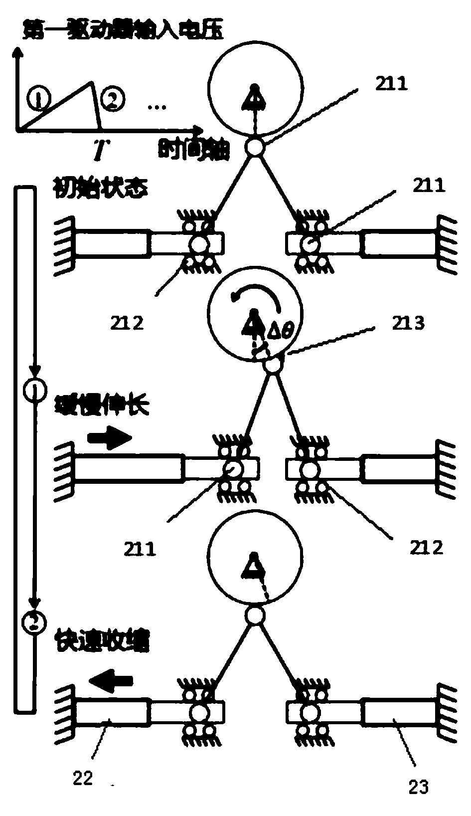
[0038] Such as image 3 and Figure 4 As shown, for counterclockwise rotation driving, the second driver 23 does not work and inputs a slowly rising and rapidly falling triangular wave voltage to the first driver 22. The reference frequency is 2.6kHz, the reference voltage is 90V, and the time ratio between the rise and fall of the reference voltage is 4 :1. When the voltage rises slowly, the first driver 22 slowly stretches, and the triangular flexible driving member 21 generates a forward motion at the driving point, which rotates the rotor 11 counterclockwise by an angle, and at the same time generates an upward parasitic motion at the driving point, Clamping the rotor 11 effectively increases the driving force when the rotor 11 rotates. When the voltage drops rapidly, the triangular flexible driving member 21 will also quickly shrink backwards with the first driver 22 at the driving point. At this time, due to the inertia of the rotor 11 itself and the downward parasitic...
PUM
 Abstract
Description
Claims
Application Information