A Magnetic Latching Solenoid Controlled Microwave Switch Driving System

A microwave switch and drive system technology, applied in the direction of electromagnetic relays, electromagnetic relay details, relays, etc., can solve the problems of large power consumption and achieve the effect of large driving stroke, high efficiency and compact structure

Active Publication Date: 2014-10-29
CHINA AEROSPACE TIMES ELECTRONICS +1
View PDF4 Cites 0 Cited by
  • Summary
  • Abstract
  • Description
  • Claims
  • Application Information

AI Technical Summary

Problems solved by technology

At present, this kind of switch mostly adopts a suction structure. The action principle of this structure is to put metal movable parts in the energized coil (only one coil). After the coil is energized, the metal parts move in the magnetic field to push the transmission mechanism to move. Return to the original position through the restoring force of the transmission mechanism. This structure requires continuous power supply to the drive coil to maintain the action state, which consumes a lot of power.

Method used


Image

  • A Magnetic Latching Solenoid Controlled Microwave Switch Driving System
  • A Magnetic Latching Solenoid Controlled Microwave Switch Driving System
  • A Magnetic Latching Solenoid Controlled Microwave Switch Driving System

Examples


Embodiment Construction

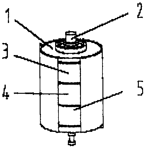
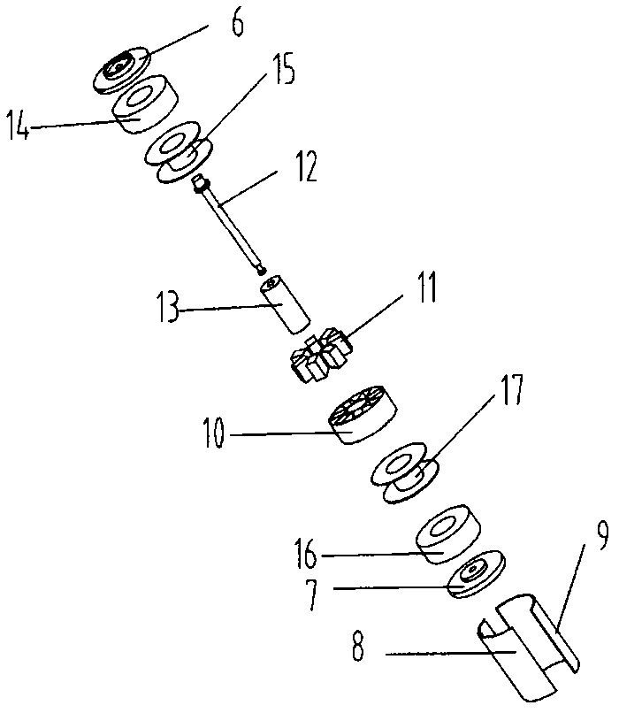
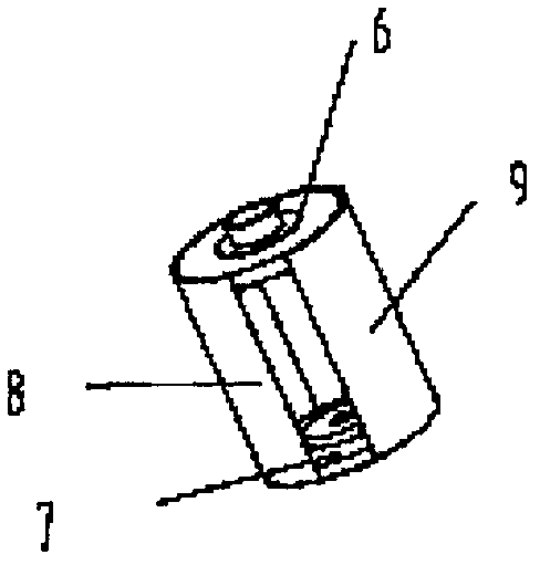
[0015] Such as figure 1 , figure 2 , image 3 , Figure 4 As shown, the driving system of the present invention mainly includes a yoke group 1, an iron core group 2, an upper coil group 3, a magnetic steel array group 4, and a lower coil group 5, which jointly form a magnetic path. The yoke group 1 includes an upper yoke 6 , a lower yoke 7 , a left yoke 8 and a right yoke 9 . The magnetic steel array group 4 includes a magnetic steel fixing frame 10 and a magnetic steel array 11 . The iron core group 2 includes an iron core 12 and a transmission shaft 13 . The upper coil assembly 3 includes an upper coil frame 15 and an upper coil 14 wound on the upper coil frame 15 . The lower coil set 5 includes a lower coil frame 17 and a lower coil 16 wound on the lower coil frame 17. The two coils each lead to two terminals.

[0016] The magnetic steel array group 4 is composed of massive magnetic steel, which is evenly distributed on the circumference and concentric to the center,...


PUM


Abstract

The invention discloses a magnetic latching type solenoid control microwave switch driving system, which mainly comprises an upper coil assembly, a lower coil assembly, a magnetic steel array group, an iron core group and a yoke group, wherein the upper coil assembly and the lower coil assembly consist of upper and lower groups of coils, of which the parameters are the same, and the encircling direction of the current of the upper and lower groups of coils are opposite; the magnetic steel array group comprises a plurality of pieces of block-type magnetic steel which are arranged along the circumference and homopolarly centripetal; the iron core group consists of a transmission shaft and an iron core relatively fixed with the transmission shaft; the magnetic steel array group encircles the iron core; the iron core group passes through the axes of magnetic stele arrays; and yokes covers a whole mechanism. Under the condition that the coils are not powered on, the driving system can keep an upper stable state and a lower stable state of the iron core group; when a pulse signal passes through the lower coils, the iron core group moves upwards from the lower state; when the pulse signal passes through the upper coils, the iron core group moves downwards from the upper state; and the travel change of the iron core group reflects switch on and switch off of a travel control microwave switch of an execution mechanism. The magnetic latching type solenoid control microwave switch driving system has the characteristics of large travel, energy saving, compact structure, small volume and the like.

Description

technical field [0001] The invention relates to a microwave switch drive system. Background technique [0002] Due to its own structural characteristics, the solenoid-controlled microwave switch has the advantage of a larger stroke than the traditional driving method. At present, this kind of switch mostly adopts a suction structure. The action principle of this structure is to put metal movable parts in the energized coil (only one coil). After the coil is energized, the metal parts move in the magnetic field to push the transmission mechanism to move. The original position is restored by the restoring force of the transmission mechanism. This structure requires continuous power supply to the drive coil to maintain the action state, which consumes a lot of power. Due to the high power of the conduction microwave signal, the high-power microwave switch has a large action stroke of the corresponding conduction part, and there is a power-saving requirement in the aerospace en...

Claims


Application Information

Patent Timeline
Patent Type & Authority Patents(China)
IPC IPC(8): H01H50/16
Inventor 田亚伟张楚贤姚延风李大鹏
Owner CHINA AEROSPACE TIMES ELECTRONICS
Why Eureka
Try Eureka