A scanning near-field optical detection platform

A technology of scanning near-field optics and detection table, applied in scanning probe technology, scanning probe microscopy, measuring device and other directions, can solve the problems of three-dimensional table movement error, motion board 1 cannot move, and errors are difficult to eliminate. , to achieve the effect of smooth driving process, overcoming small driving stroke and reducing manufacturing precision requirements

Active Publication Date: 2015-12-09
南通新微研究院 +1
View PDF5 Cites 0 Cited by
  • Summary
  • Abstract
  • Description
  • Claims
  • Application Information

AI Technical Summary

Problems solved by technology

In actual work, there are inevitably errors in the position and direction of the point of action of the force F, and there are inevitably errors in the manufacture of the flexible hinge mechanism. There is mutual coupling between them, and the sports board 1 cannot move strictly in the x direction
[0004] The existing 3D scanning mobile workbench generally has multiple (usually 3) parallelogram flexible hinges arranged orthogonally to each other, and the components are connected in a solid state. Due to the complex coupling of the movement and force of each dimension, There is inevitably a certain error in the movement of the three-dimensional worktable, and this error is difficult to eliminate
The micro-drive of the existing 3D scanning mobile workbench generally adopts piezoelectric crystal driver, which has high driving precision, but the effective stroke is very small, so it needs to be equipped with a coarse motion device, and the mechanism is relatively complicated

Method used


Image

  • A scanning near-field optical detection platform
  • A scanning near-field optical detection platform
  • A scanning near-field optical detection platform

Examples


Embodiment Construction

[0034] Embodiments of the present invention are described below through specific examples, and those skilled in the art can easily understand other advantages and effects of the present invention from the content disclosed in this specification. The present invention can also be implemented or applied through other different specific implementation modes, and various modifications or changes can be made to the details in this specification based on different viewpoints and applications without departing from the spirit of the present invention.

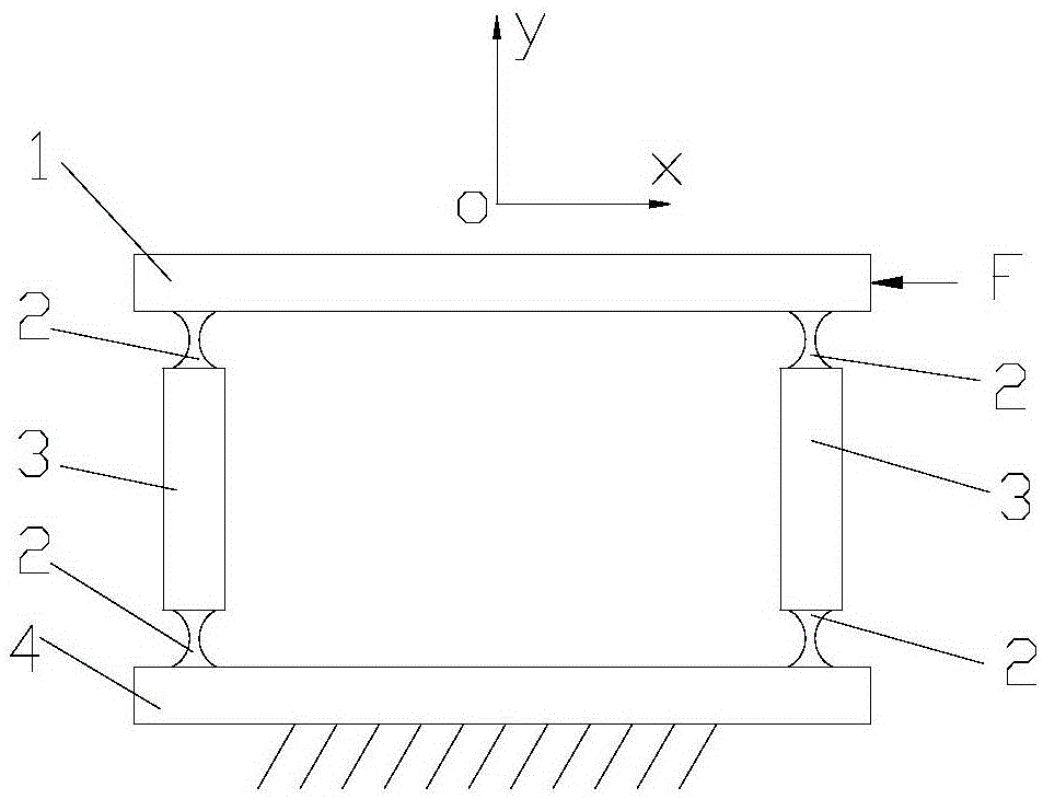
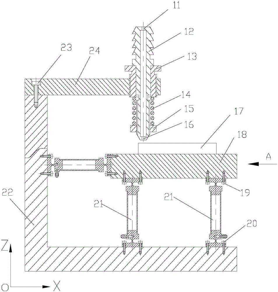
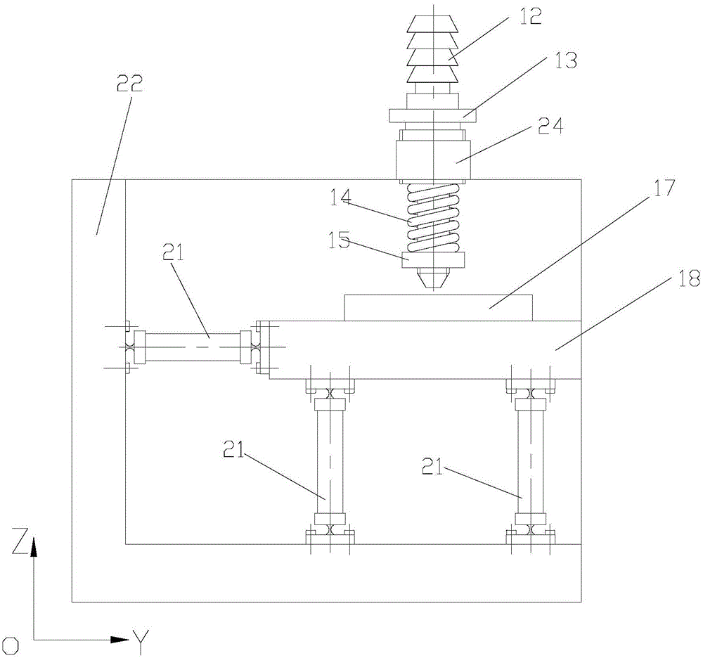
[0035] see Figure 1 to Figure 6 shown. It should be noted that the diagrams provided in this embodiment are only schematically illustrating the basic idea of ​​the present invention, and only the components related to the present invention are shown in the diagrams rather than the number, shape and shape of the components in actual implementation. Dimensional drawing, the type, quantity and proportion of each component can be change...


PUM


Abstract

The invention provides a scanning near-field optical detecting table which comprises a body (22) and a rectangular operation platform (18). The body comprises an XOY face, a YOZ face and a ZOX face. The XOY face, the YOZ face and the ZOX face are perpendicular to one another. Containing space is defined by the XOY face, the YOZ face and the ZOX face. The rectangular operation platform (18) used for containing workpieces (17) is contained in the containing space. The rectangular operation platform comprises a bottom face and four side faces, wherein every two adjacent side faces are perpendicular to each other. The four corners of the bottom face of the rectangular operation platform are provided with four hydraulic driving units (21) fixed to the XOY face of the body. The two adjacent side faces of the rectangular operation platform are provided with two hydraulic driving units (11) fixed to the YOZ face and the ZOX face of the body respectively. The YOZ face is provided with a nozzle unit located above the workpieces and used for achieving positioning of the workpieces in the Z-axial direction. According to the scanning near-field optical detecting table, the elongation of a strut is adjustable and detectable, so that the accuracy of displacement of the operation platform is high, control is simple, and the effective travel of motion of the operation platform is large.

Description

technical field [0001] The invention relates to the field of optical mechanics, in particular to a scanning near-field optical detection device. Background technique [0002] With the increasing integration of modern optical systems, the scale of optical design structures is constantly decreasing. For sub-wavelength optical structures, the range of light fields that need to be detected is usually on the order of microns, and optical microscopes are no longer competent due to the limitation of the diffraction limit. A scanning near-field optical microscope based on optical probe technology provides a solution, which mainly includes a positioning module, a displacement module and a light field receiving and detecting module. Its main working principle is: the optical fiber probe is used to detect the coupled light field, which is fixed on the displacement device, and the optical probe is scanned within a certain range near the sample surface by controlling the positioning and...

Claims


Application Information

Patent Timeline
Patent Type & Authority Patents(China)
IPC IPC(8): G01Q60/18
Inventor 黄海阳武爱民甘甫烷盛振李伟
Owner 南通新微研究院
Why Eureka
Try Eureka