
Clutch arrangement, and drive train unit

A clutch assembly, drive train technology, used in clutches, friction clutches, mechanical drive clutches, etc.

Active Publication Date: 2020-01-17
ZF FRIEDRICHSHAFEN AG
View PDF5 Cites 0 Cited by
  • Summary
  • Abstract
  • Description
  • Claims
  • Application Information

AI Technical Summary

Problems solved by technology

This has the disadvantage that the electric motor must retain a corresponding power reserve to be able to switch from electric to hybrid operation or to operate the combustion engine alone

Method used


Image

  • Clutch arrangement, and drive train unit
  • Clutch arrangement, and drive train unit
  • Clutch arrangement, and drive train unit

Examples


Embodiment Construction

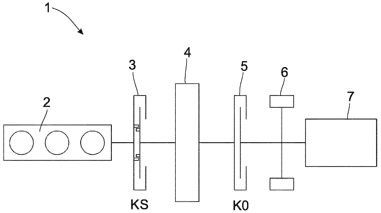
[0041] figure 1 A drive train 1 with an internal combustion engine 2 , a flywheel launch clutch assembly 3 , a flywheel mass arrangement 4 , a disconnect clutch 5 , an electric motor 6 and a gearbox 7 is shown. The electric motor 6 can be designed here as a single electric motor or as a series electric motor, it is important here that the electric motor 6 acts upstream of the gearbox 7 in the drive train 1 .

[0042] The flywheel launch clutch assembly 3 is characterized by its location upstream of the flywheel mass arrangement 4 . This is due to the special function of the flywheel clutch assembly 3 , which is only used for high strokes of the internal combustion engine 2 and otherwise transmits the torque of the internal combustion engine 2 . By presetting the flywheel clutch assembly 3 , the electric motor 6 can be designed with a small power reserve and thus can be manufactured at low cost. In this case, during purely electric operation, the flywheel clutch assembly 3 se...


PUM


Abstract

The invention relates to a clutch arrangement (3) having a friction clutch (8) and a jaw clutch (9), characterized in that the output side of the friction clutch (8) and the output side of the jaw clutch (9) can be connected to a flywheel mass device (4). Furthermore, the invention relates to a drive train unit.

Description

technical field [0001] The present invention relates to a clutch assembly having a friction clutch and a dog clutch. Background technique [0002] In known clutch packs, a friction clutch and a dog clutch are connected in parallel. The torque that cannot be transmitted by the friction clutch alone can be transmitted by the dog clutch. [0003] It is also known to use electric motors in hybrid drive trains in order to start the internal combustion engine. This has the disadvantage that the electric motor must retain a corresponding power reserve in order to be able to switch from electric operation to hybrid operation or operation of the internal combustion engine alone. Correspondingly, the electric motor is designed to be more powerful than is required for operation of the electric motor alone. Contents of the invention [0004] Proceeding from this, the object of the present invention is to provide a clutch arrangement by means of which an electric motor can be used w...

Claims


Application Information

Patent Timeline
Patent Type & Authority Applications(China)
IPC IPC(8): F16D11/10F16D23/04
CPCF16D11/10F16D23/04F02N5/04F02N11/00F02N15/022B60K6/48B60K2006/4825B60K6/387B60K6/30Y02T10/62B60Y2200/92B60Y2300/50F02N11/04F03G3/08F16D11/14F16D13/22F16D21/00
Inventor G·施米特A·巴塔W·孔德尔曼A·罗姆G·菲尔内克斯A·保内M·罗斯纳M·孔茨
Owner ZF FRIEDRICHSHAFEN AG
Learn More