

Output-voltage-adjustable electric vehicle charging pile and charging voltage adjusting method
An output voltage, electric vehicle technology, applied in the direction of electric vehicle charging technology, electric vehicles, charging stations, etc., can solve the problem that the voltage cannot be fully identified.
- Summary
- Abstract
- Description
- Claims
- Application Information
AI Technical Summary
Problems solved by technology
Method used
Image

Examples
Embodiment 1
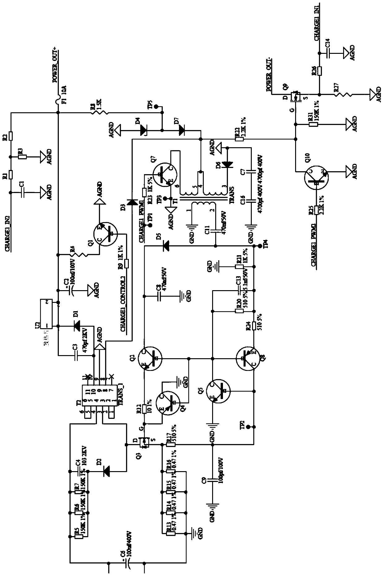
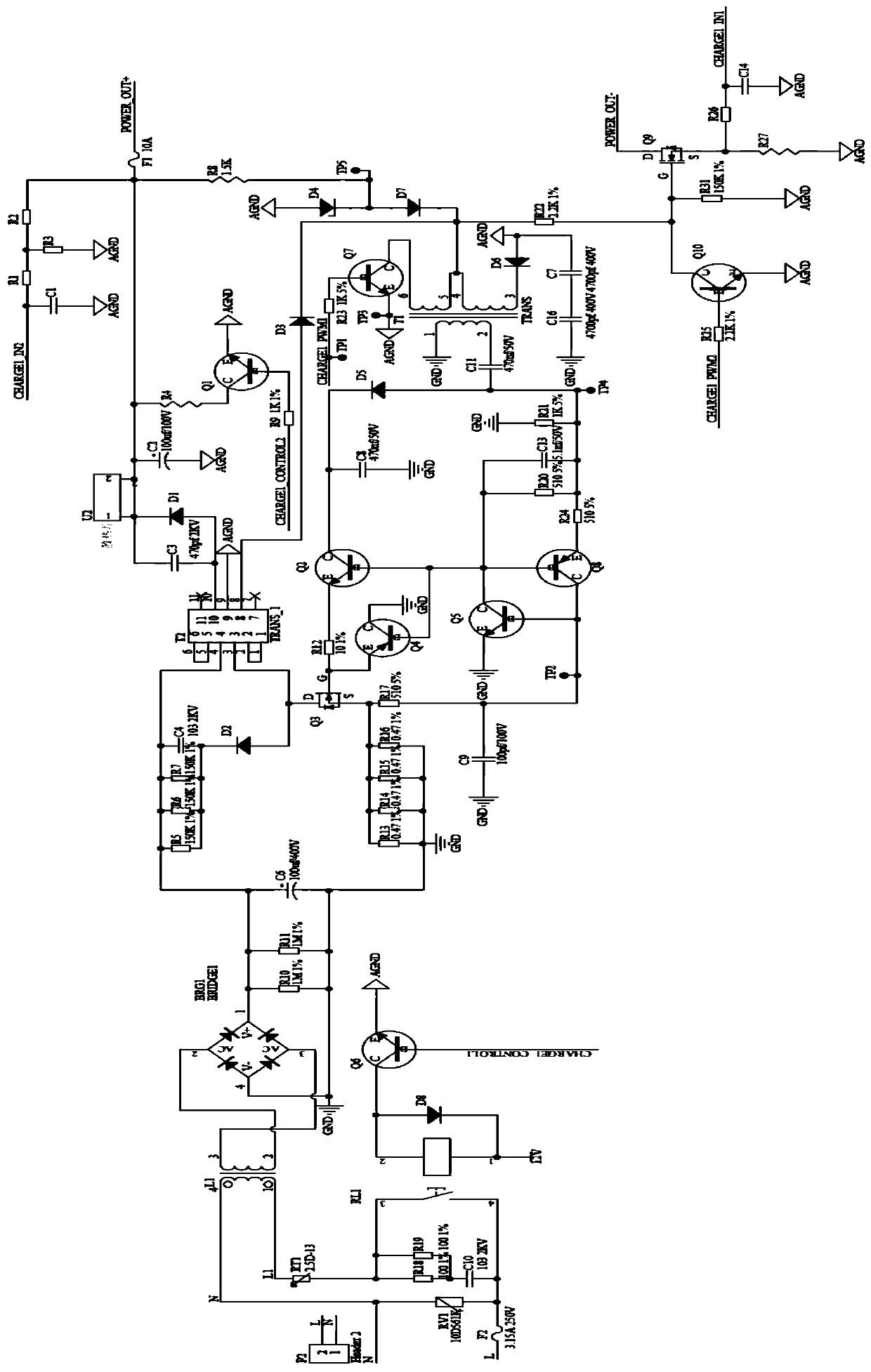
[0034] Such as figure 1 and figure 2 As shown, an electric vehicle charging pile with adjustable output voltage in this embodiment includes a casing and a charging circuit board arranged in the casing; the charging circuit board includes a charging circuit, a main control MCU, and a voltage signal acquisition circuit , Current signal acquisition circuit and PWM signal feedback circuit;
[0035] The model of the main control MCU can use some existing processors, such as the main control MCU model STM32429IGTX, refer to Figure 5 ; As long as there is an existing processor that can identify and process the received voltage signal and feed back the PWM signal containing voltage information to the PWM signal feedback circuit.
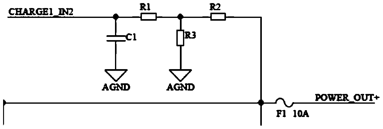
[0036] refer to figure 1, the charging circuit includes a transformer T2, and the transformer T2 is connected with an input terminal, a positive output terminal POWEROUT+ and a negative output terminal POWER OUT-. Pin 10 of the transformer is sequentia...
Embodiment 2
[0044] A method for regulating charging voltage, comprising the steps of:
[0045] A. The voltage signal acquisition circuit collects the voltage of the electric vehicle battery and sends it to the main control MCU; the main control MCU judges the range of the collected voltage according to the collected voltage signal of the battery pack; if the collected voltage is within the exclusive range of the battery pack voltage If the voltage specification of the battery pack is obtained directly, enter step B1; if the collected voltage is within the intersection range between the battery pack composed of N single storage batteries and the battery pack composed of N+1 single storage batteries, enter Step B2.
[0046] B1. According to the voltage specification of the battery pack, the main control MCU controls the transformer T2 to adjust to the charging voltage matching the battery pack through the PWM signal feedback circuit.
[0047] B2. The main control MCU controls the transform...
PUM
 Abstract
Description
Claims
Application Information