Novel steel dam

A new type of steel dam technology, applied in water conservancy projects, marine engineering, coastline protection, etc., can solve the problems of rubber dams that do not block water, silt, and take a long time to lift the dam.

Pending Publication Date: 2020-01-21
YANGZHOU CITY FIDELITY HYDRAULIC MACHINERY
View PDF0 Cites 1 Cited by
  • Summary
  • Abstract
  • Description
  • Claims
  • Application Information

AI Technical Summary

Problems solved by technology

[0002] With the development of society, water resources are becoming more and more tense. In order to make full use of water resources, dams are usually built in river courses, but this does not affect flood control safety. Among the types of dams, although the cost of automatic flap dams is low, the operation and management Convenience and other advantages, but there are many problems in automatic flap dams, water blocking, easy to cause siltation, rubber dams do not block water, and the cost is not high, but they are easy to damage, take a long time to raise the dam, and have poor safety and reliability. Steel dams The gate includes the dam face plate, the bottom shaft at the bottom of the dam face plate and the control devices on both sides of the dam face plate. The control device controls the rotation of the bottom shaft to drive the opening and closing of the dam face plate with flat structure. The panel is an integral structure, mostly for the opening and closing of small-scale gates, and the range of turning angles is small. At the same time, if pedestrians need to cross the river, another bridge needs to be erected on the top of the steel dam, which is costly and inconvenient for flood discharge. In addition, in the closed state There is no locking mechanism for locking, these problems have to be solved, so it needs to be improved

Method used


Image

  • Novel steel dam
  • Novel steel dam

Examples


Embodiment Construction

[0014] The present invention will be described in further detail below in conjunction with the accompanying drawings.

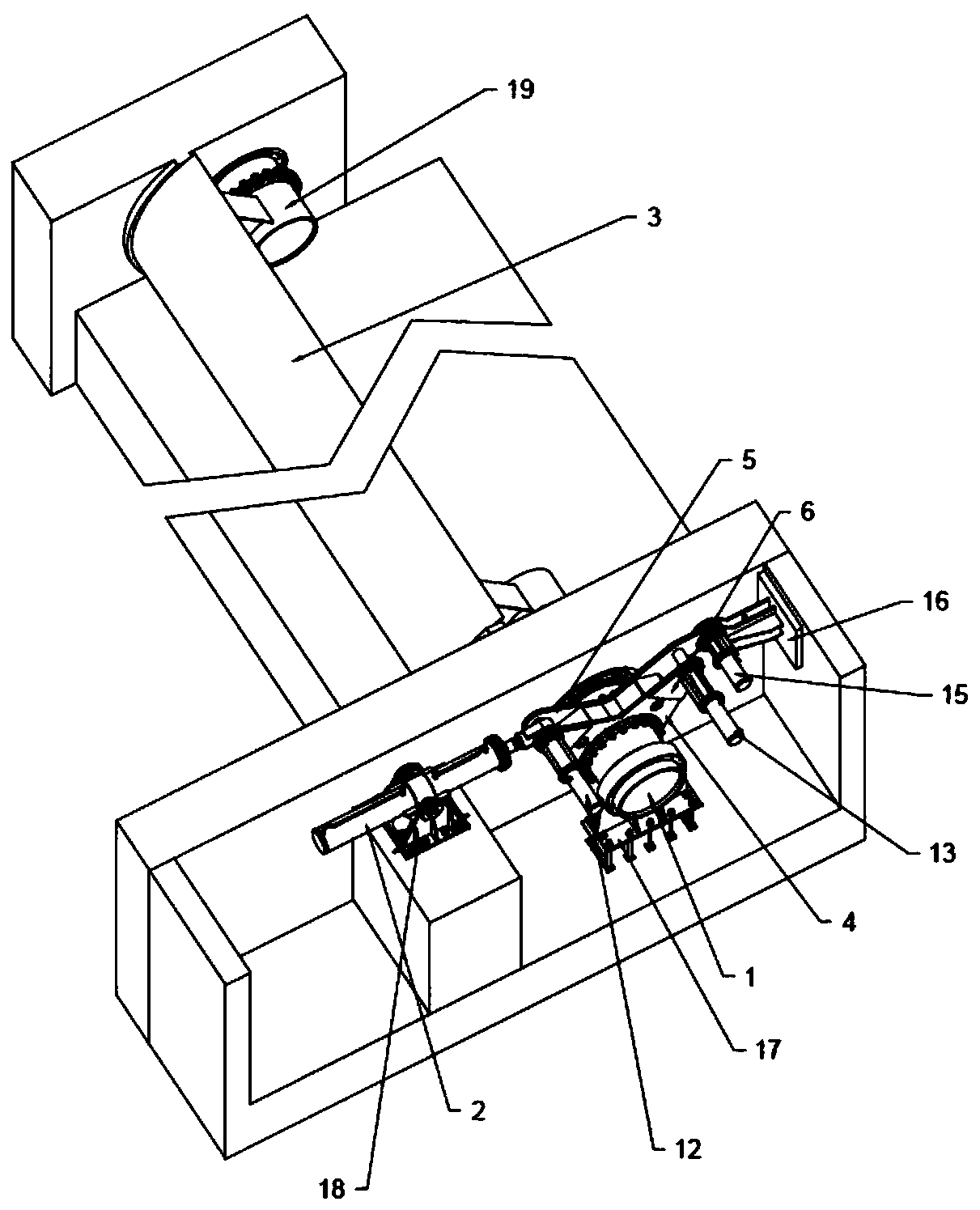
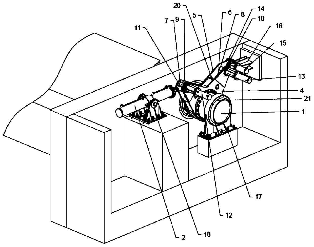
[0015] In practice, the present invention provides a new type of steel dam, including a rotating shaft 1 and a hydraulic column 2. One end of the rotating shaft 1 is fixedly sleeved with a gate blade 3 with an arc-shaped section, and the rotating shaft 1 is far away from the gate. One side of the leaf plate 3 is fixedly sleeved with a starting arm 4, and the two sides of the starting arm 4 are respectively fixed with a V-shaped lug one 5 and lug two 6, and the two ends of the lug one 5 are respectively Through hole 1 7 and through hole 2 8 are provided, and the two ends of the ear plate 6 correspond to the through hole 1 7 and through hole 2 8 respectively. Through hole 3 9 and through hole 4 10 are provided. The hydraulic column The end of the piston rod 2 is fixed with a piston rod earring 11, and the outer wall of the ear plate 2 6 is fixed with a hydrauli...


PUM


Abstract

The invention discloses a novel steel dam. The novel steel dam comprises a rotary shaft and a hydraulic column. One end of the rotary shaft is fixedly sleeved with a gate vane plate with the arc-shaped section, one side of the rotary shaft is fixedly sleeved with a starting arm, a first lug plate and a second lug plate are fixedly arranged on the two sides of the starting arm separately, a pistonrod lug ring is fixedly arranged at the end of a piston rod of the hydraulic column, a first hydraulic rod and a second hydraulic rod are fixedly arranged on the outer side wall of the second lug plate, a fixing hole is formed in the first lug plate, a third hydraulic rod is fixedly arranged on the side wall of the first lug plate, the end, close to the fixing hole, of the first lug plate is sleeved with a fixing frame, the end, away from the gate vane plate, of the rotary shaft is sleeved with a supporting seat, a base is fixedly hinged to the middle of the hydraulic column, and the other endof the gate vane plate is sleeved with a supporting shaft. Compared with the prior art, the novel steel dam has the beneficial effects that according to the novel steel dam, people can walk on the gate vane plate, a gate can rotate at a large angle, and closure can be stably locked.

Description

technical field [0001] The invention relates to the technical field of hydraulic steel dams, in particular to a novel steel dam. Background technique [0002] With the development of society, water resources are becoming more and more tense. In order to make full use of water resources, dams are usually built in river courses, but this does not affect flood control safety. Among the types of dams, although the cost of automatic flap dams is low, the operation and management Convenience and other advantages, but there are many problems in automatic flap dams, water blocking, easy to cause siltation, rubber dams do not block water, and the cost is not high, but they are easy to damage, take a long time to raise the dam, and have poor safety and reliability. Steel dams The gate includes the dam face plate, the bottom shaft at the bottom of the dam face plate and the control devices on both sides of the dam face plate. The panel is an integral mechanism, mostly for the opening ...

Claims


Application Information

Patent Timeline
Patent Type & Authority Applications(China)
IPC IPC(8): E02B7/02E02B7/40
CPCE02B7/02E02B7/40
Inventor 刘飞蔡立明
Owner YANGZHOU CITY FIDELITY HYDRAULIC MACHINERY
Why Eureka
Try Eureka