
Sloping roof M type splicing grout blocking steel plate and construction method thereof

A construction method and technology for inclined roofs, which are applied to roofs, roof coverings, and roof engineering tools, can solve problems such as shortened service life of structures, short initial setting time, and structural safety, so as to save construction costs and reduce The effect of construction period and easy operation

Active Publication Date: 2020-01-21
CHINA FIRST METALLURGICAL GROUP
View PDF4 Cites 0 Cited by
  • Summary
  • Abstract
  • Description
  • Claims
  • Application Information

AI Technical Summary

Problems solved by technology

However, in this traditional concrete pouring method for sloped roofs, because the concrete slump will change the characteristics of the concrete, there are often hidden quality problems, such as segregation, short initial setting time and other concrete-related quality problems. After the final setting of the concrete, internal due to Quality problems There are a lot of cracks, which not only cause major quality problems, but also shorten the service life of the structure, which may lead to structural safety problems in the later stage

Method used


Image

  • Sloping roof M type splicing grout blocking steel plate and construction method thereof
  • Sloping roof M type splicing grout blocking steel plate and construction method thereof
  • Sloping roof M type splicing grout blocking steel plate and construction method thereof

Examples


Embodiment Construction

[0036] The following will clearly and completely describe the technical solutions in the embodiments of the present invention with reference to the accompanying drawings in the embodiments of the present invention. Obviously, the described embodiments are only some, not all, embodiments of the present invention. Based on the embodiments of the present invention, all other embodiments obtained by persons of ordinary skill in the art without making creative efforts belong to the protection scope of the present invention.

[0037] It should be noted that the experimental methods described in the following embodiments, unless otherwise specified, are conventional methods, and the reagents and materials, if not otherwise specified, can be obtained from commercial sources; in the description of the present invention, The terms "landscape", "portrait", "top", "bottom", "front", "rear", "left", "right", "vertical", "horizontal", "top", "bottom", The orientation or positional relations...


PUM


Abstract

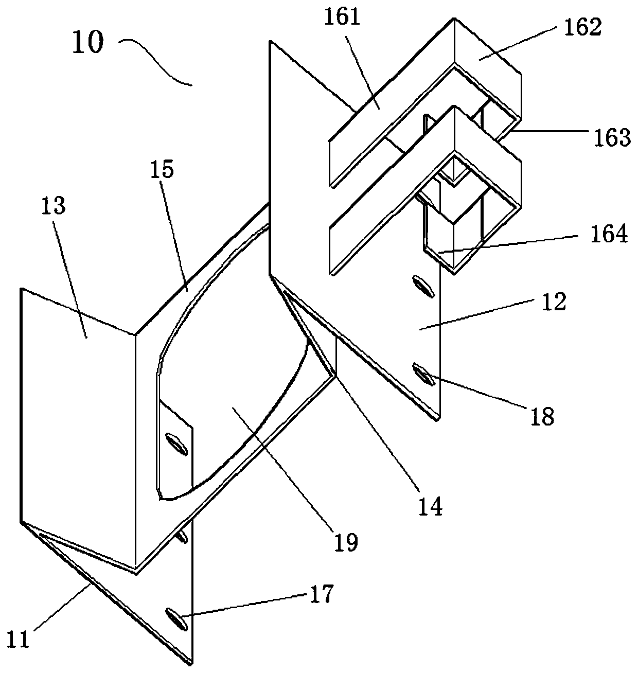
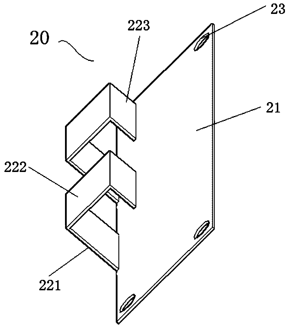
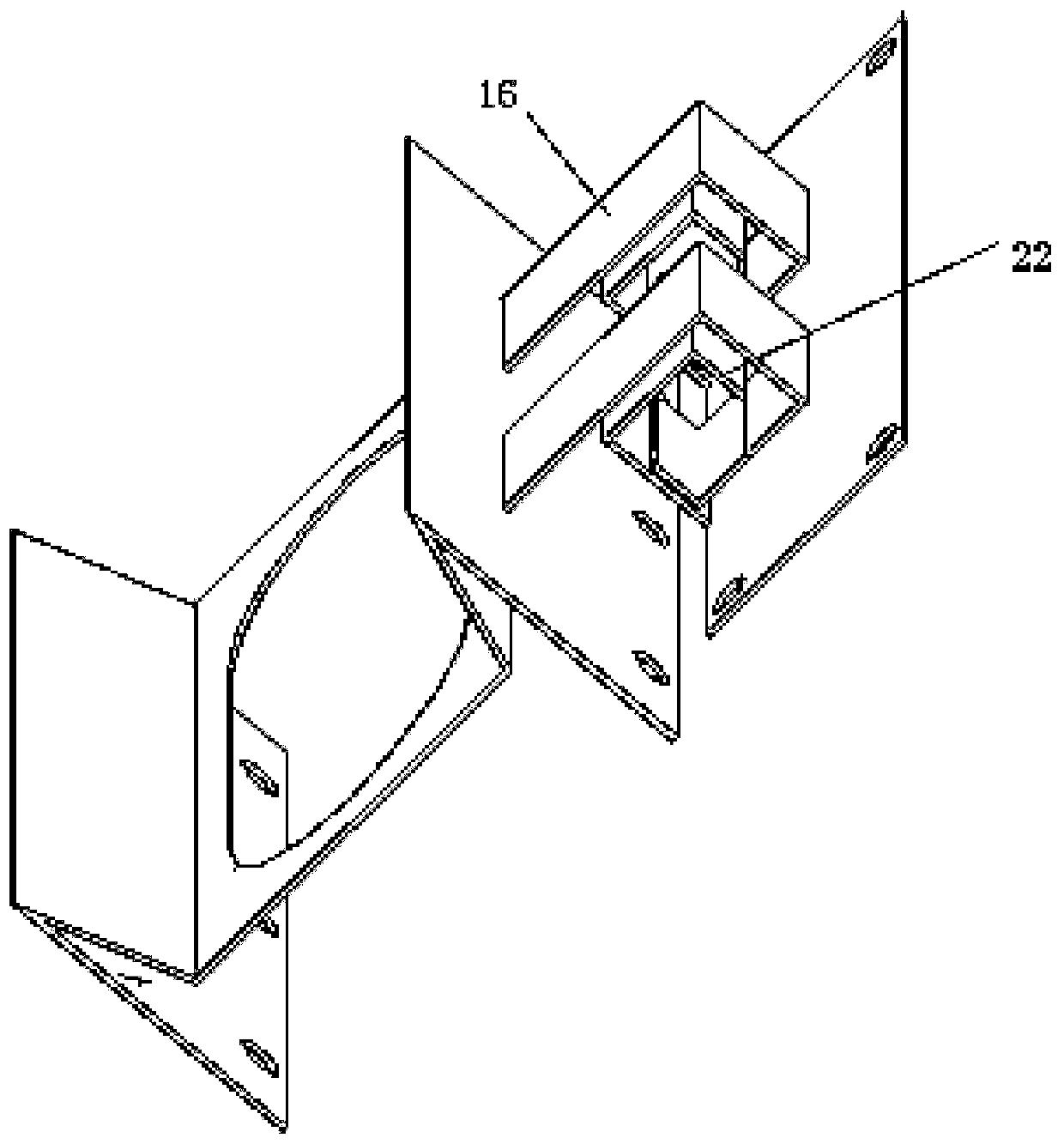
The invention discloses a sloping face M type splicing grout blocking steel plate and a construction method thereof. The sloping face M type splicing grout blocking steel plate comprises a lower baffle and an upper baffle, the lower baffle and the upper baffle are detachably connected. The lower baffle is in a 90-degree rotating M shape and comprises a first horizontal plate and a second horizontal plate which are symmetrically arranged in parallel. The first horizontal plate is fixedly connected with a first inclined plate, and the second horizontal plate is fixedly connected with a second inclined plate. A vertical plate perpendicular to the first horizontal plate and the second horizontal plate is fixedly connected between the first inclined plate and the second inclined plate. First bent buckles are fixedly connected to the second horizontal plate. By means of the sloping roof M type splicing grout blocking steel plate and the construction method thereof, the flowing rate of concrete poured a sloping roof can be indirectly reduced, the concrete vibration density is ensured, and in addition, the number of construction seams can be effectively reduced during layered pouring. Meanwhile, the steel plate can be a supporting object for double-layer bidirectional board steel bars of the sloping roof, and the effective thickness of the steel bars on a sloping roof structure board is effectively ensured. Operation is convenient, the cost is relatively low, the technology is simple, safety and reliability are achieved, the economical efficiency and practicability are achieved, and potential safety hazards of a sloping roof concrete structure are effectively avoided.

Description

technical field [0001] The invention relates to the technical field of sloping roof construction, in particular to an M-shaped assembled grout-retaining steel plate for sloping roofs and a construction method thereof. Background technique [0002] With the development of the economy and the improvement of people's living standards, various housing constructions such as commercial housing and resettlement housing are becoming more and more common. In order to improve the aesthetics of the building, the main body of the general building usually increases the aesthetics of the main body by designing a sloping roof. As one of the main decorative structures of the house, the sloped roof often has frequent water leakage problems due to poor concrete pouring quality. At present, in the construction process of concrete pouring on sloped roofs of buildings, in order to improve the quality of concrete pouring on sloped roofs, technical measures are often used to change the slump of co...

Claims


Application Information

Patent Timeline
Patent Type & Authority Applications(China)
IPC IPC(8): E04D15/07E04D7/00
CPCE04D7/00E04D15/07
Inventor 汪城城霍其赞李俊杰曾维才
Owner CHINA FIRST METALLURGICAL GROUP
Learn More