
Speed reducer structure

A reducer and oil leakage prevention technology, which is applied in the direction of mechanical equipment, transmission parts, belts/chains/gears, etc., can solve problems such as throwing out, lubricating oil leakage, and influence on the operation of the reducer, and achieve the effect of preventing loss

Inactive Publication Date: 2020-01-21
江苏众力合创精密机械科技有限公司
View PDF5 Cites 0 Cited by
  • Summary
  • Abstract
  • Description
  • Claims
  • Application Information

AI Technical Summary

Problems solved by technology

The lubricating oil after lubrication is easy to be thrown out when the reducer is running at high speed, resulting in leakage of the lubricating oil. Once the excessive leakage of the lubricating oil will seriously affect the operation of the reducer

Method used


Image

  • Speed reducer structure
  • Speed reducer structure

Examples


Embodiment Construction

[0017] The present invention is further described in conjunction with the following examples.

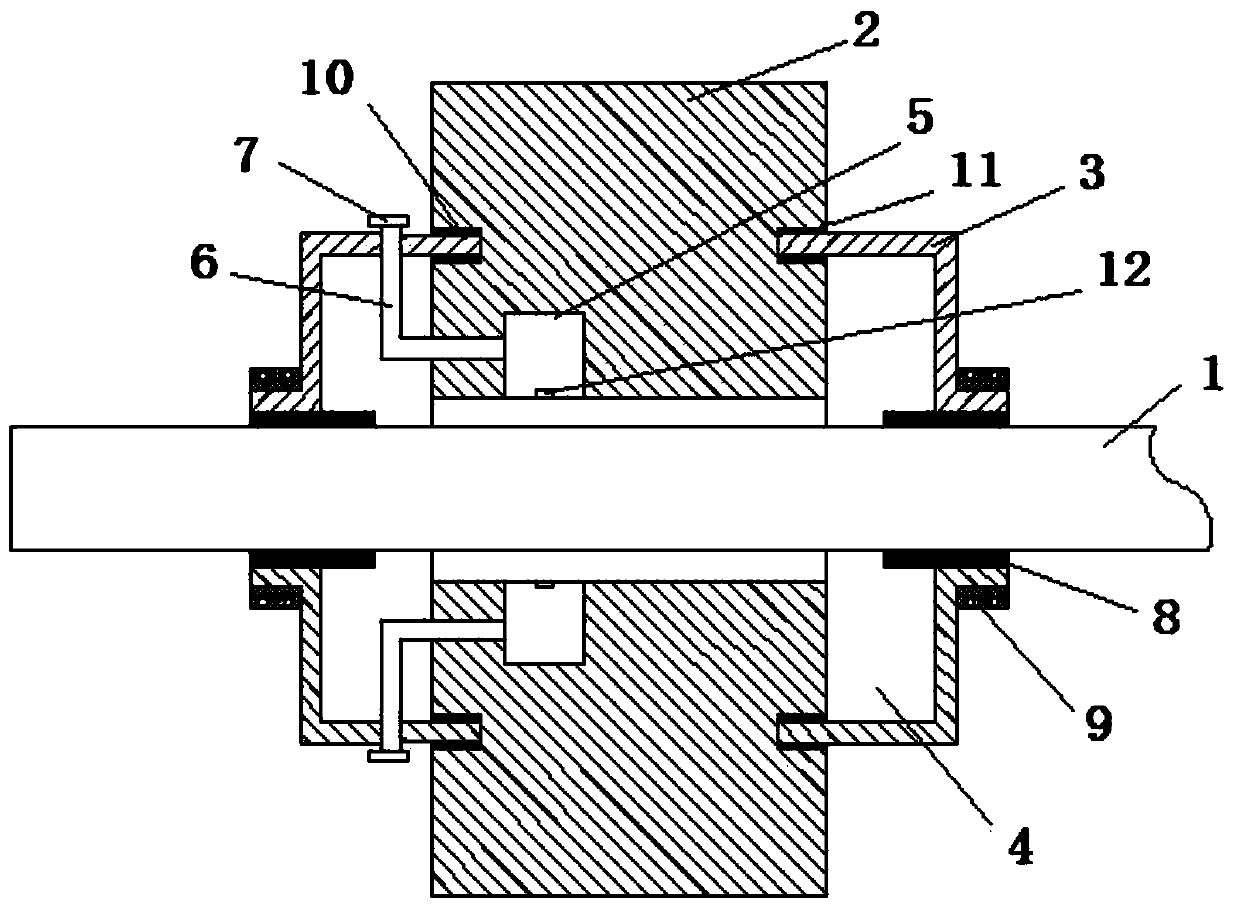
[0018] see figure 1 The embodiment of the present invention provides a reducer structure, the reducer structure includes a reducer shaft 1 and a bearing 2, and the reducer shaft 1 is rotatably mounted on the bearing 2.

[0019] The structure of the reducer also includes an oil leakage protection cover 3, which is installed on the outer end of the bearing 2 to prevent the lubricant from volatilizing from the contact between the bearing 2 and the shaft 1 of the reducer. , evaporate to the outside.

[0020] A cavity 4 is formed between the anti-leakage protection cover 3 and the reducer shaft 1 and the bearing 2, and the bearing 2 is provided with a lubricating oil storage chamber 5 communicating with the reducer shaft 1. The lubricating oil storage chamber 5 communicates with one end of an oil injection pipe 6 , and the other end of the oil injection pipe 6 passes through the oil le...


PUM


Abstract

The invention relates to the technical field of speed reducers, and provides a speed reducer structure. The speed reducer structure comprises a speed reducer rotating shaft and a bearing, wherein thespeed reducer rotating shaft is rotatably mounted on the bearing. The speed reducer structure is characterized by further comprising an oil leakage preventing protective cover, wherein the oil leakagepreventing protective cover is mounted at the outer end of the bearing; a cavity is formed among the oil leakage preventing protective cover, the speed reducer rotating shaft and the bearing; a lubricating oil storage cavity which communicates with the speed reducer rotating shaft is formed in the bearing; the lubricating oil storage cavity communicates with one end of an oil injecting tube; theother end of the oil injecting tube penetrates through the oil leakage preventing protective cover from the cavity; and a sealing cover is detachably arranged at the other end of the oil injecting tube. According to the speed reducer structure disclosed by the invention, the oil leakage preventing protective cover can prevent lubricating oil volatilized at a contact position of the bearing and thespeed reducer rotating shaft from leaking to the outside, so that the loss of the lubricating oil is prevented.

Description

technical field [0001] The invention relates to the technical field of reducers, in particular to a structure of a reducer. Background technique [0002] In the prior art, for the good operation of the reducer, the joint between the rotating shaft and the bearing of the reducer needs to be lubricated, and lubricating oil is commonly used. The lubricated lubricating oil is easy to be thrown out when the reducer is running at high speed, resulting in leakage of the lubricating oil. Once the lubricating oil leaks excessively, it will seriously affect the operation of the reducer. Contents of the invention [0003] In view of the above problems, the present invention provides a reducer structure. [0004] The object of the present invention adopts following technical scheme to realize: [0005] The invention provides a reducer structure, which includes a reducer shaft and a bearing, and the reducer shaft is rotatably mounted on the bearing. [0006] The reducer structure al...

Claims


Application Information

Patent Timeline
IPC IPC(8): F16H57/029F16H57/021F16H57/04
CPCF16H57/021F16H57/029F16H57/0421F16H57/045F16H57/0471
Inventor 方为堂
Owner 江苏众力合创精密机械科技有限公司
Features
  • Generate Ideas
  • Intellectual Property
  • Life Sciences
  • Materials
  • Tech Scout
  • Unparalleled Data Quality
  • Higher Quality Content
  • 60% Fewer Hallucinations
Learn More