Electrothermal blowing dry box

An electric heating blast drying and blower technology, which is applied in the directions of drying gas arrangement, local stirring dryer, static material dryer, etc., can solve the problem of not setting temperature and humidity sensors, reducing drying speed and quality, and inability to accurately reflect box utensils. Whether to dry and other issues, to achieve the effect of convenient and accurate temperature adjustment, improve energy utilization, and prevent heat loss

Inactive Publication Date: 2015-12-23
湖州周吴鼎盛化工有限公司
View PDF11 Cites 20 Cited by
  • Summary
  • Abstract
  • Description
  • Claims
  • Application Information

AI Technical Summary

Problems solved by technology

[0002] Electric drying oven, also known as "oven", is used in various industries such as chemical industry, electronics, casting, automobile, food, machinery, etc., for baking, drying, curing, heat treatment and other convenient heating of various products and samples. Not applicable For volatile items, in order to avoid explosion, the electric heating method is used to carry out the blast cycle drying test. The existing electric blast drying ovens generally set the heater under the drying rack, so that the temperature in the drying oven rises too slowly, and the moisture The evaporation is slow, and because there is no heater at the upper end of the box, the temperature difference between the upper end and the lower end of the box is too large, and it is difficult to fully dry, which greatly reduces the drying speed and quality, and there is no setting in the general geothermal blast drying box. The temperature and humidity sensor cannot accurately reflect whether the utensils placed in the box are dry, and it is easy to damage the utensils and cause danger. With the progress of society, people now have higher and higher requirements for equipment and more precise temperature control

Method used


Image

  • Electrothermal blowing dry box
  • Electrothermal blowing dry box
  • Electrothermal blowing dry box

Examples


Embodiment Construction

[0016] The following will clearly and completely describe the technical solutions in the embodiments of the present invention with reference to the accompanying drawings in the embodiments of the present invention. Obviously, the described embodiments are only some, not all, embodiments of the present invention. Based on the embodiments of the present invention, all other embodiments obtained by persons of ordinary skill in the art without making creative efforts belong to the protection scope of the present invention.

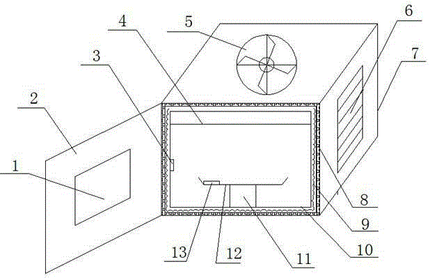
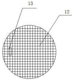
[0017] see figure 1 , the present invention provides a technical solution: an electric blast drying box, comprising a box door 2, a blower 5 and a box body 7, the top of the box body 7 is provided with a blower 5, and the right side of the box body 7 is provided with a heat dissipation Window 6, a rotating platform 11 is arranged inside the box body 7, a tray 12 is arranged above the rotating platform 11, a humidity sensor 13 is arranged on the tray 12, and a ...


PUM


Abstract

The invention discloses an electrothermal blowing dry box. The electrothermal blowing dry box comprises a box door, an air blower and a box body, wherein the air blower is arranged at the top of the box body; a radiating window is arranged at the right side of the box body; a rotating platform is arranged in the box body; a tray is arranged above the rotating platform; a humidity inductor is arranged on the tray; a temperature inductor is arranged on the inner wall of the box body; a protection plate is arranged at the upper part of the box body; air dispersing holes are uniformly distributed on the protection plate; the box door is arranged at the left side of the box body; an observation window is arranged at the middle part of the box door; a liquid crystal display screen is arranged at the left side of the box door; and an operation panel is arranged below the liquid crystal display screen. The electrothermal blowing dry box is reasonable in structure and practical in function; as the rotating platform is arranged, products are uniformly heated, and the temperature in the box is low in disturbance; electric heating wires are used for heating, so that the temperature adjustment is convenient and precise; and as the heat preservation layer is arranged, the heat loss can be effectively prevented, and the energy utilization rate is largely improved.

Description

technical field [0001] The invention relates to the field of drying equipment, in particular to an electric blast drying oven. Background technique [0002] Electric drying oven, also known as "oven", is used in various industries such as chemical industry, electronics, casting, automobile, food, machinery, etc., for baking, drying, curing, heat treatment and other convenient heating of various products and samples. Not applicable For volatile items, in order to avoid explosion, the electric heating method is used to carry out the blast cycle drying test. The existing electric blast drying ovens generally set the heater under the drying rack, so that the temperature in the drying oven rises too slowly, and the moisture The evaporation is slow, and because there is no heater at the upper end of the box, the temperature difference between the upper end and the lower end of the box is too large, and it is difficult to fully dry, which greatly reduces the drying speed and qualit...

Claims


Application Information

Patent Timeline
Patent Type & Authority Applications(China)
IPC IPC(8): F26B9/06F26B21/00F26B23/06
Inventor 泮连江
Owner 湖州周吴鼎盛化工有限公司
Why Eureka
Try Eureka