
High-efficiency heat dissipation device for PCB case

A heat dissipation device and high-efficiency technology, applied in cooling/ventilation/heating transformation, circuit arrangement on support structure, electrical components, etc. Pressure, solve the effect of poor heat dissipation

Pending Publication Date: 2020-01-21
苏州市惠利盛电子科技有限公司
View PDF0 Cites 0 Cited by
  • Summary
  • Abstract
  • Description
  • Claims
  • Application Information

AI Technical Summary

Problems solved by technology

[0004] The purpose of the present invention is to provide a high-efficiency heat dissipation device for a PCB case to solve the problem of single heat dissipation method and poor heat dissipation effect in the above background technology

Method used


Image

  • High-efficiency heat dissipation device for PCB case
  • High-efficiency heat dissipation device for PCB case
  • High-efficiency heat dissipation device for PCB case

Examples


Embodiment Construction

[0022] The following will clearly and completely describe the technical solutions in the embodiments of the present invention with reference to the accompanying drawings in the embodiments of the present invention. Obviously, the described embodiments are only some, not all, embodiments of the present invention.

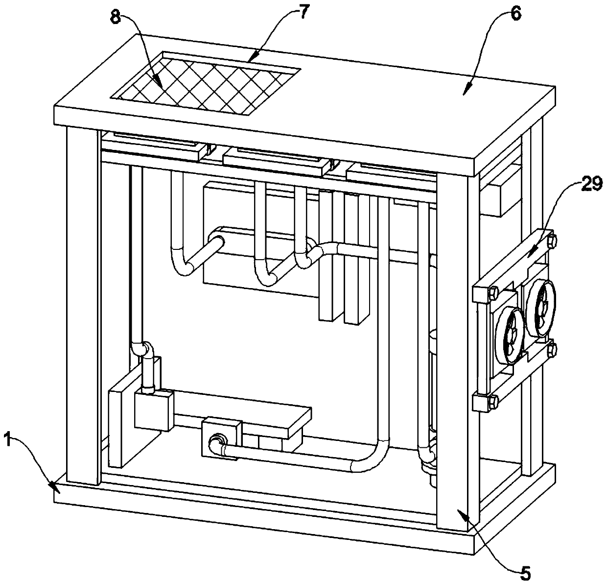
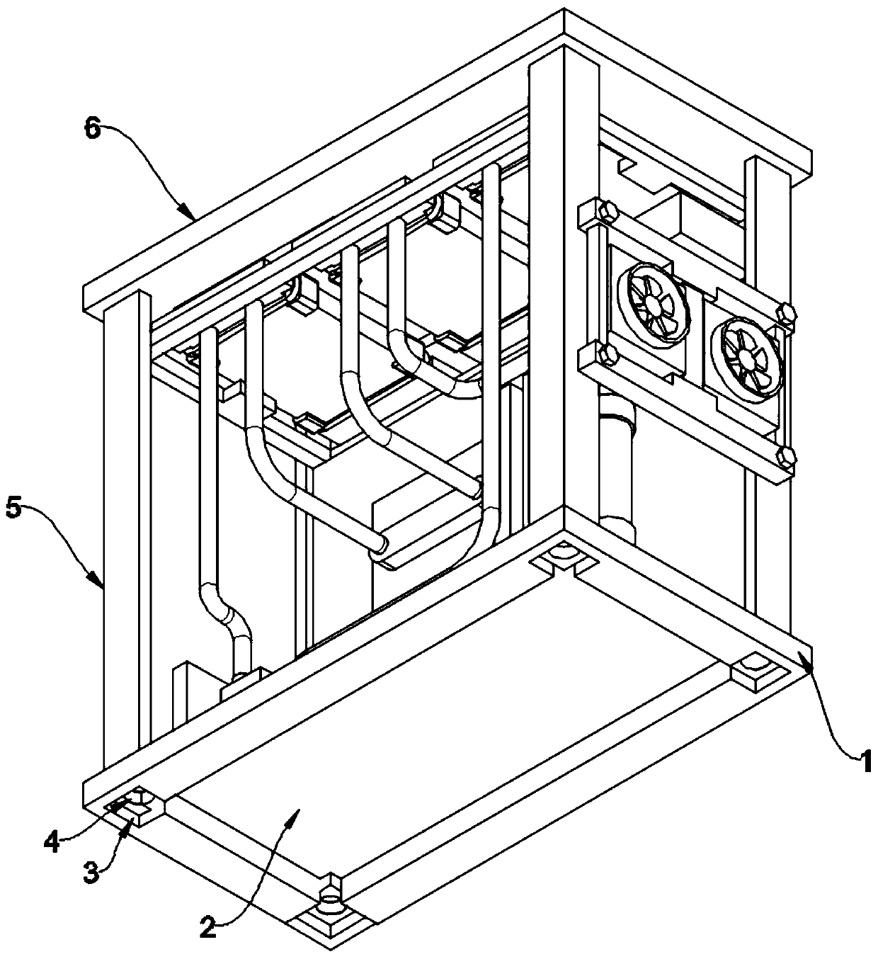
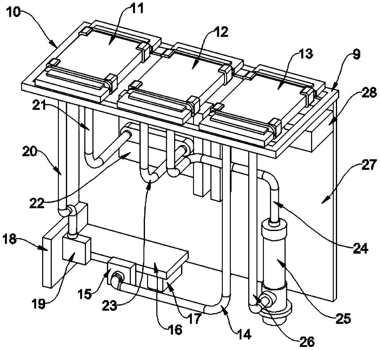
[0023] see Figure 1-5 , an embodiment provided by the present invention: a high-efficiency heat dissipation device for a PCB case, including a water cooling assembly 9, the water cooling assembly 9 includes a cold row fixing plate 10, and a first cold row 11 is arranged on the cold row fixing plate 10, and the first cooling row The row 11 is attached to the cold row fixing plate 10, the second cold row 12 is arranged on one side of the first cold row 11, the third cold row 13 is arranged on one side of the second cold row 12, the first cold row 11, the second cold row The second cold row 12 and the third cold row 13 have the same shape and size. The third cold row 1...


PUM


Abstract

The invention discloses a high-efficiency heat dissipation device for a PCB case and relates to the technical field of network information equipment in order to solve the poor heat dissipation effectof a unitary heat dissipation method in the prior art. A water cooling component includes a radiator fixing plate. A first radiator is disposed on the radiator fixing plate and is bonded to the radiator fixing plate. A second radiator is disposed on a side of the first radiator. A third radiator is disposed on a side of the second radiator. The first radiator, the second radiator, and the third radiator are configured to have the same shape and size. The third radiator is provided with a third radiator water discharge pipe fixedly connected to the third radiator. The rear end of the third radiator water discharge pipe is provided with a cooling plate water inlet plate. A water tank is disposed in the cooling plate water inlet plate.

Description

technical field [0001] The invention relates to the related field of network information equipment technology, in particular to a high-efficiency heat dissipation device for a PCB case. Background technique [0002] PCB, the Chinese name is printed circuit board, also known as printed circuit board, is an important electronic component, a support for electronic components, and a carrier for electrical connections of electronic components. Devices, and through the arrangement of the heat conduction layer, these electronic components are separated into each cell, and multiple electronic components in each cell form a functional unit with relatively independent functions, that is, each unit The grid corresponds to a functional unit, and each functional unit exerts its own performance during work to achieve its own function. Therefore, PCB technology is also widely used in the field of electronic equipment, but the existing PCB case is prone to damage after working for a long ti...

Claims


Application Information

Patent Timeline
IPC IPC(8): H05K7/20H05K7/02
CPCH05K7/20145H05K7/20272H05K7/20172H05K7/02
Inventor 辛健
Owner 苏州市惠利盛电子科技有限公司
Learn More