
Positioning plate for garment processing and cutting

A positioning plate and clothing technology, applied in the direction of sewing tools and other directions, can solve the problems of skewed fabric cutting, waste of time, and difficult alignment of fabrics, and achieve the effect of avoiding fabric movement.

Inactive Publication Date: 2020-01-24
ANHUI HEFEI AUTO FORGING
View PDF10 Cites 0 Cited by
  • Summary
  • Abstract
  • Description
  • Claims
  • Application Information

AI Technical Summary

Problems solved by technology

[0004] The existing cutting and positioning template is composed of a pressing plate and a bearing plate. There are cutting holes respectively on the pressing plate and the supporting plate. The cutting holes are determined according to the length of the required shoulder strap cloth. Align the cutting holes on the board, and use a scissors to cut along the cutting holes, but the existing cutting and positioning templates are not easy to align the cloth during use, so it is a waste of time during use, and it is easy to cut the cloth The cutting is crooked. Therefore, a positioning board for garment processing and cutting is proposed

Method used


Image

  • Positioning plate for garment processing and cutting
  • Positioning plate for garment processing and cutting
  • Positioning plate for garment processing and cutting

Examples


Embodiment Construction

[0029] The following will clearly and completely describe the technical solutions in the embodiments of the present invention with reference to the accompanying drawings in the embodiments of the present invention. Obviously, the described embodiments are only some, not all, embodiments of the present invention. Based on the embodiments of the present invention, all other embodiments obtained by persons of ordinary skill in the art without making creative efforts belong to the protection scope of the present invention.

[0030] see Figure 1-6 , the present invention provides a technical solution:

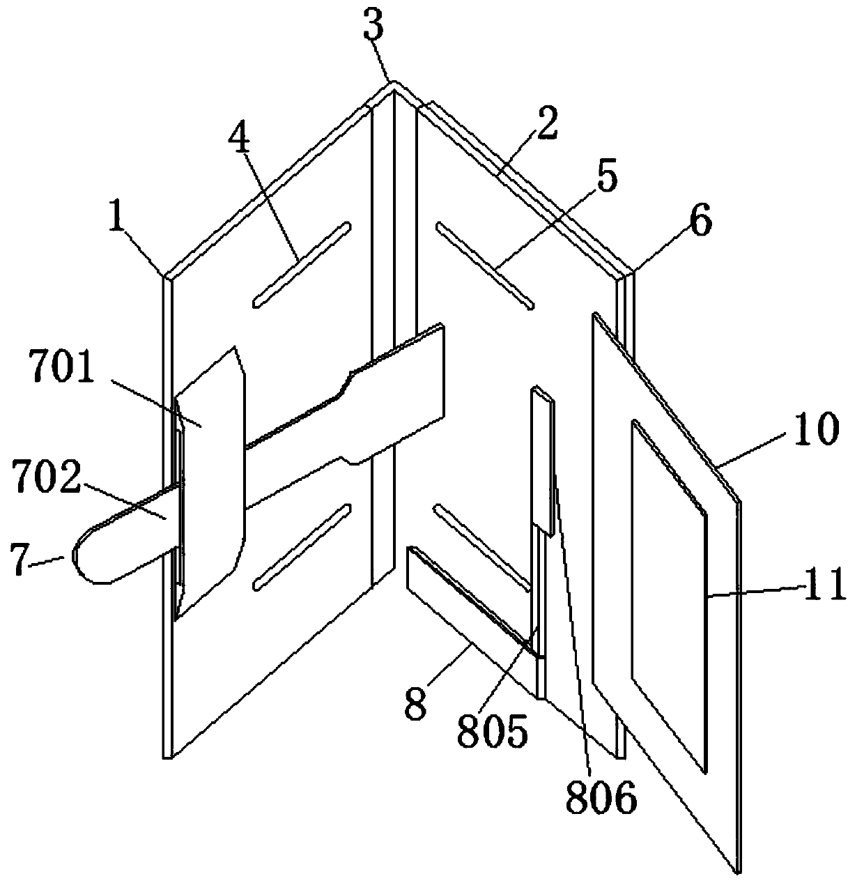
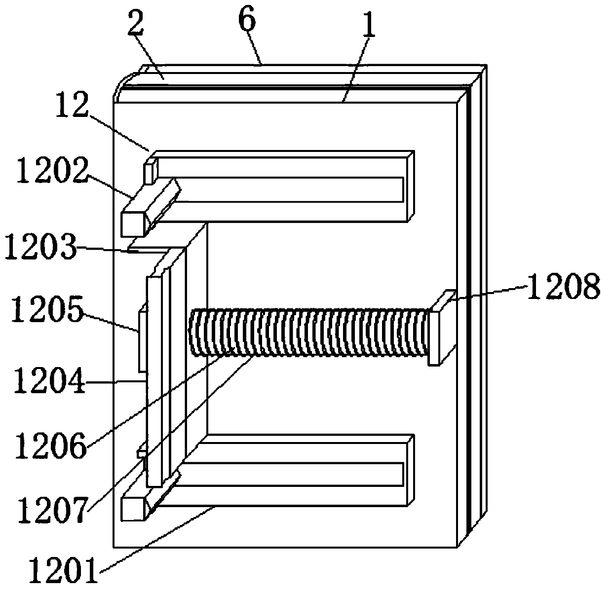
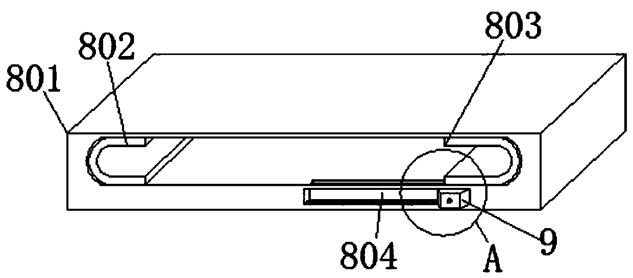
[0031] A positioning plate for garment processing and cutting, comprising a pressing plate 1, a loading plate 2 and a connecting piece 3, the pressing plate 1 and the loading plate 2 are connected through the connecting piece 3, so that the pressing plate 1 can be turned around the loading plate 2, and the pressing plate 1 can be opened and closed Above, the first cutting hole 4 i...


PUM


Abstract

The invention discloses a positioning plate for garment processing and cutting. The positioning plate comprises a pressing plate, a bearing plate and a connecting piece, wherein the pressing plate andthe bearing plate are connected through the connecting piece, so that the pressing plate can be turned over around the bearing plate; a first limiting mechanism is connected to the pressing plate, sothat one side of cut cloth is limited; the first limiting mechanism comprises a blocking piece and a movable sleeve; the movable sleeve is fixedly connected to the side wall of one side of the pressing plate; and one end of the blocking piece movably penetrates through the movable sleeve, and the other end of the blocking piece is fixedly connected to the bearing plate. According to the positioning plate, the two sides of the shoulder belt cloth are limited through mutual cooperation of the first limiting mechanism and a second limiting mechanism; and in the operation process, the shoulder belt cloth is placed on the bearing plate firstly, one side of the shoulder belt cloth is limited by the blocking piece, the shoulder belt cloth is placed between a first limiting block and a second limiting block in a mounting frame, and the other side of the shoulder belt cloth is limited by a second blocking block, so that the situation that the shoulder belt cloth is not easily aligned in the cutting process is avoided and the phenomenon of skewing is avoided.

Description

technical field [0001] The invention relates to the technical field of garment production equipment, in particular to a positioning plate for garment processing and cutting. Background technique [0002] The camouflage uniform is the clothing worn by the school military training and the soldiers in the army, and the shoulder strap is a part of the camouflage uniform. When the camouflage uniform is produced, the fabric needs to be cut into pieces of shoulder strap cloth, and then the shoulder strap cloth is sewed. Shaped, and finally the shoulder straps are sewn together with the shoulders of the garment. [0003] In the process of cutting the shoulder strap cloth, it is necessary to cut the cloth into the required width first, and then cut the shoulder strap cloth into the required length. In the production process of the workshop, the operator often takes the discarded cloth Stacked together, and then further cut into a rectangle of a certain width, and the rectangular sho...

Claims


Application Information

Patent Timeline
Patent Type & Authority Applications(China)
IPC IPC(8): A41H3/01
CPCA41H3/01
Inventor 钟亚军郑明玉王东东
Owner ANHUI HEFEI AUTO FORGING
Learn More