Supercharge Your Innovation With Domain-Expert AI Agents!

Auxiliary temperature control device, temperature regulation system and temperature regulation method

A temperature control device and temperature adjustment technology, applied in the field of passenger aircraft, can solve the problems of poor occupant comfort, low heat exchange efficiency, and increased cost, and achieve the effects of ensuring comfort, improving heat exchange efficiency, and reducing flow resistance

Active Publication Date: 2020-01-24
COMAC +1
View PDF8 Cites 0 Cited by
  • Summary
  • Abstract
  • Description
  • Claims
  • Application Information

AI Technical Summary

Problems solved by technology

The disadvantages of this scheme are: 1) The heat exchanger is installed on the air supply duct of the recirculation system. Due to the limitation of the space size in the pipeline layout, the heat exchange efficiency is low and the flow resistance is high; 2) This scheme can only To provide additional cooling capacity, the auxiliary heating cannot be achieved when the heating of the air conditioner is insufficient; 3) The auxiliary refrigeration system is connected to a single pipeline (such as a recirculation pipeline), and when the air supply of the corresponding pipeline is lost, the ability to supplement the additional cooling capacity 4) In the flight state of emergency ventilation, this scheme cannot adjust the temperature of the emergency ram air from the outside world which is too cold or too hot, and the comfort of the occupants is poor, and extreme hot or cold weather will cause damage to the occupants
The performance degradation of air-conditioning equipment brings increased costs and inconvenience to aircraft operations

Method used


Image

  • Auxiliary temperature control device, temperature regulation system and temperature regulation method
  • Auxiliary temperature control device, temperature regulation system and temperature regulation method
  • Auxiliary temperature control device, temperature regulation system and temperature regulation method

Examples


Embodiment Construction

[0045] Referring now to the accompanying drawings, specific embodiments of the present invention will be described in detail. What is described here is only a preferred embodiment of the present invention, and those skilled in the art can think of other ways to realize the present invention on the basis of the preferred embodiments, and the other ways also fall within the scope of the present invention.

[0046] The invention provides an auxiliary temperature control device, a temperature adjustment system including the auxiliary temperature control device, and a temperature adjustment method realized based on the system.

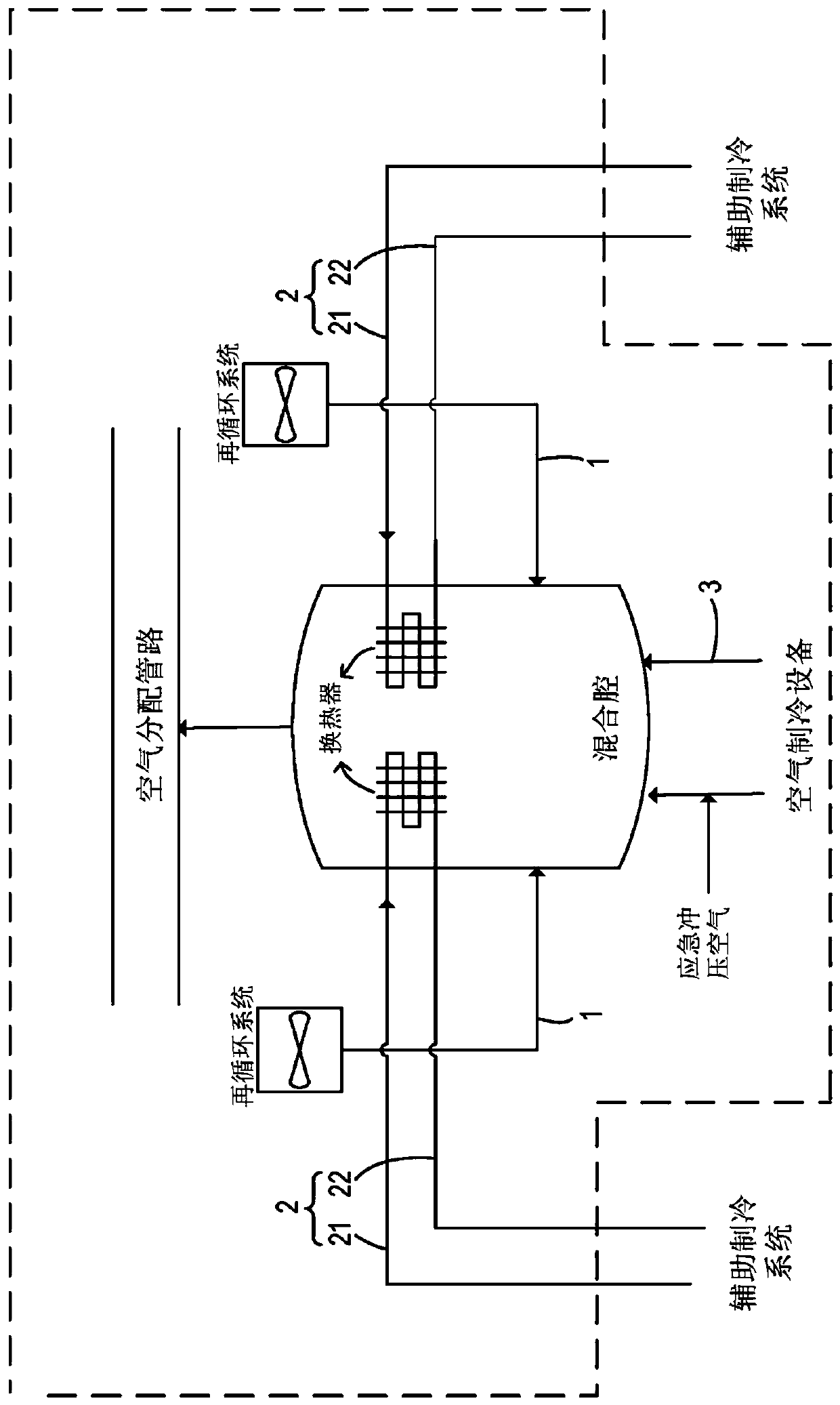
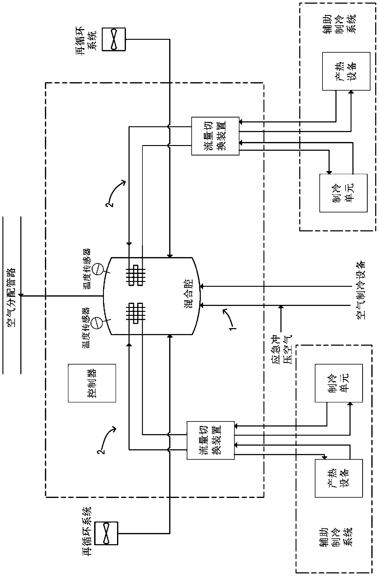
[0047] refer to figure 2 and image 3 , the auxiliary temperature control device includes a mixing chamber, a heat exchanger built in the mixing chamber, a first pipeline 1 connecting the mixing chamber and the recirculation system, a second pipeline 2 connecting the mixing chamber and the auxiliary refrigeration system, and the The pipeline switching de...


PUM


Abstract

The invention provides an auxiliary temperature control device, a temperature regulation system and a temperature regulation method. The auxiliary temperature control device comprises a mixing chamber, a heat exchanger, a first pipeline, a second pipeline and a pipeline switching device, wherein the heat exchanger is arranged in the mixing chamber and can enable heat exchange between fluid from anauxiliary refrigerating system and gas in the mixing chamber; the first pipeline is connected between the mixing chamber and a recirculation system; the second pipeline is connected between the mixing chamber and the auxiliary refrigerating system and is independent of the first pipeline; and the pipeline switching device is arranged on the second pipeline and can control the flow direction of fluid in the second pipeline. According to the auxiliary temperature control device, the fluid pipeline connected with the mixing chamber and the auxiliary refrigerating system is independent of the pipeline used for air extraction from the recirculation system, so that the auxiliary refrigerating system can still play a temperature regulating role for the gas in the mixing chamber in case of the failure of an air extraction pipeline of the recirculation system.

Description

technical field [0001] The invention relates to the field of passenger aircraft, in particular to an auxiliary temperature control device for an aircraft cockpit, a temperature regulation system including the device and a temperature regulation method based on the system. Background technique [0002] Generally, the bleed air system of civil aircraft generally uses air conditioning equipment to provide cooled and heated air to the cabin. When the cooling capacity of air conditioning equipment is limited, an auxiliary refrigeration system is usually used to provide additional cooling capacity. [0003] The structure of the existing air-conditioning equipment is figure 1 is shown in , where temperature control is achieved by heat exchange between the auxiliary refrigeration system and the recirculated air. The disadvantages of this scheme are: 1) The heat exchanger is installed on the air supply duct of the recirculation system. Due to the limitation of the space size in the...

Claims


Application Information

Patent Timeline
IPC IPC(8): B64D13/06
CPCB64D13/06B64D2013/0603Y02T50/50
Inventor 任重远沈祥唐慧儒简夕忠郭琪黄星
Owner COMAC
Features
  • R&D
  • Intellectual Property
  • Life Sciences
  • Materials
  • Tech Scout
  • Unparalleled Data Quality
  • Higher Quality Content
  • 60% Fewer Hallucinations
Learn More