Material collecting device for drying and crushing equipment

A crushing equipment and collection device technology, which is applied in the field of material collection devices for dry crushing equipment, can solve the problems of poor dust-proof effect, difficulty in moving, time-consuming and labor-intensive, etc., and achieves easy to move and carry, good dust-proof function, and guaranteed stability Effect

Inactive Publication Date: 2020-01-24
太仓市友联干燥粉碎设备有限公司
View PDF0 Cites 4 Cited by
  • Summary
  • Abstract
  • Description
  • Claims
  • Application Information

AI Technical Summary

Problems solved by technology

[0003] However, the material collection device of the existing equipment of this type has a simple structure, and usually only an open material receiving barrel is placed under the equipment, so that the processed materials are exposed to the air, resulting in poor dustproof effect, and It is not easy to move and needs to be carried manually, which is time-consuming, laborious and inconvenient. Therefore, we propose a material collection device for dry crushing equipment

Method used


Image

  • Material collecting device for drying and crushing equipment
  • Material collecting device for drying and crushing equipment
  • Material collecting device for drying and crushing equipment

Examples


Embodiment 1

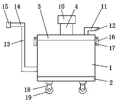
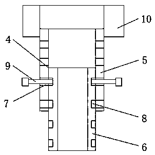
[0022] Reference Figure 1-3 , A material collection device for drying and crushing equipment, comprising a collection bucket 1. The lower surface of the collection bucket 1 is fixedly connected with a base 2, and the upper surface of the collection bucket 1 is fixedly installed with a dust-proof bucket cover 3, and the upper surface of the dust-proof bucket cover 3 A height adjustment mechanism 4 and a dust-proof pressure discharge pipe 11 are installed on the surface. The height adjustment mechanism 4 includes a fixed pipe 6 fixedly connected to the dust-proof bucket cover 3, and the top of the fixed pipe 6 is movably sleeved with a movable sleeve 5 and a movable sleeve 5 Both vertical inner surfaces of the two sides are provided with insertion holes 7, and both vertical outer walls of the fixed pipe 6 are provided with a card slot 8. The insertion pin 9 and a height adjustment mechanism 4 are inserted into the insertion hole 7 and the card slot 8. A threaded connection pipe 1...

Embodiment 2

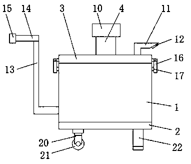
[0028] Reference Figure 2-3 , A material collection device for drying and crushing equipment, comprising a collection bucket 1, a base 2 is fixedly connected to the lower surface of the collection bucket 1, a dust-proof bucket cover 3 is fixedly installed on the upper surface of the collection bucket 1, and the upper surface of the dust-proof bucket cover 3 A height adjustment mechanism 4 and a dust-proof pressure discharge pipe 11 are installed on the surface. The height adjustment mechanism 4 includes a fixed pipe 6 fixedly connected to the dust-proof bucket cover 3, and the top of the fixed pipe 6 is movably sleeved with a movable sleeve 5 and a movable sleeve 5 Both vertical inner surfaces of the two sides are provided with insertion holes 7, and both vertical outer walls of the fixed pipe 6 are provided with a card slot 8. The insertion pin 9 and a height adjustment mechanism 4 are inserted into the insertion hole 7 and the card slot 8. A threaded connection pipe 10 is th...


PUM


Abstract

The invention discloses a material collecting device for drying and crushing equipment. The material collecting device comprises a collecting barrel, wherein the lower surface of the collecting barrelis fixedly connected with a base; a dustproof barrel cover is fixedly mounted on the upper surface of the collecting barrel; a height regulating mechanism and a dustproof pressure discharge tube aremounted on the upper surface of the dustproof barrel cover; the height regulating mechanism comprises a fixed tube which is fixedly connected with the dustproof barrel cover; the top of the fixed tubeis movably connected with a movable sleeve in a sleeving mode; insertion holes are formed in vertical inner surfaces at the two sides of the movable sleeve; blocking slots are formed in vertical outer walls at the two sides of the fixed tube; positioning bolts are inserted into the insertion holes and the blocking slots; and the outer surface of the top of the height regulating mechanism is in threaded connection with a threaded connecting tube. The collecting device has a good dustproof function, can be freely regulated according to discharge heights of different drying and crushing equipment, is convenient for people to move and carry, and also can stop moving when needed, so that stability of the collecting device is guaranteed.

Description

Technical field [0001] The invention relates to the technical field of drying and crushing equipment, and in particular to a material collection device for drying and crushing equipment. Background technique [0002] Feed includes more than ten varieties of feed materials such as soybean, soybean meal, corn, fish meal, amino acids, miscellaneous meal, additives, whey powder, oil, meat and bone meal, grains, sweet sorghum, etc. The feed requires two or more The raw materials are stirred and mixed and then crushed, and then the crushed materials are dried. At present, people usually use crushing vacuum dryers to dry and crush feed. [0003] However, the existing material collection device of this type of equipment has a simple structure, usually only an open receptacle is placed under the equipment, which causes the processed materials to be exposed to the air, resulting in poor dust-proof effects and It is not easy to move and needs to be carried manually, which is time-consuming a...

Claims


Application Information

Patent Timeline
Patent Type & Authority Applications(China)
IPC IPC(8): B65D90/14B65D90/18B65D90/32B65D90/54B65D88/54B02C23/00
CPCB02C23/00B65D88/54B65D90/14B65D90/18B65D90/32B65D90/54
Inventor 柏建荣
Owner 太仓市友联干燥粉碎设备有限公司
Why Eureka
Try Eureka