Lift rope head damping device

A vibration damping device and rope head technology, which is applied in transportation and packaging, spring/shock absorber, vibration suppression adjustment, etc., can solve the problems of increasing vibration energy transfer efficiency, poor vibration isolation efficiency, poor noise reduction and vibration isolation effect, etc. problem, to achieve the effect of improving the effect of noise reduction and vibration isolation, and reducing the natural frequency

Pending Publication Date: 2020-01-24
SCHINDLER CHINA ELEVATOR CO LTD
View PDF0 Cites 1 Cited by
  • Summary
  • Abstract
  • Description
  • Claims
  • Application Information

AI Technical Summary

Problems solved by technology

[0003] However, the vibration isolation efficiency of the existing rope damping device is poor, and the dynamic stiffness of the rope is relatively large when the elevator is running, which will increase the first-order nat

Method used


Image

  • Lift rope head damping device
  • Lift rope head damping device

Examples


Embodiment Construction

[0017] In the following, the technical solutions of the present invention will be further described in detail through embodiments and in conjunction with the drawings. In the specification, the same or similar reference numerals indicate the same or similar components. The following description of the embodiments of the present invention with reference to the accompanying drawings is intended to explain the general inventive concept of the present invention, and should not be understood as a limitation to the present invention.

[0018] In addition, in the following detailed description, for the convenience of explanation, many specific details are set forth to provide a comprehensive understanding of the embodiments of the present disclosure. Obviously, however, one or more embodiments can also be implemented without these specific details. In other cases, well-known structures and devices are shown in the form of illustrations to simplify the drawings.

[0019] According to a g...


PUM


Abstract

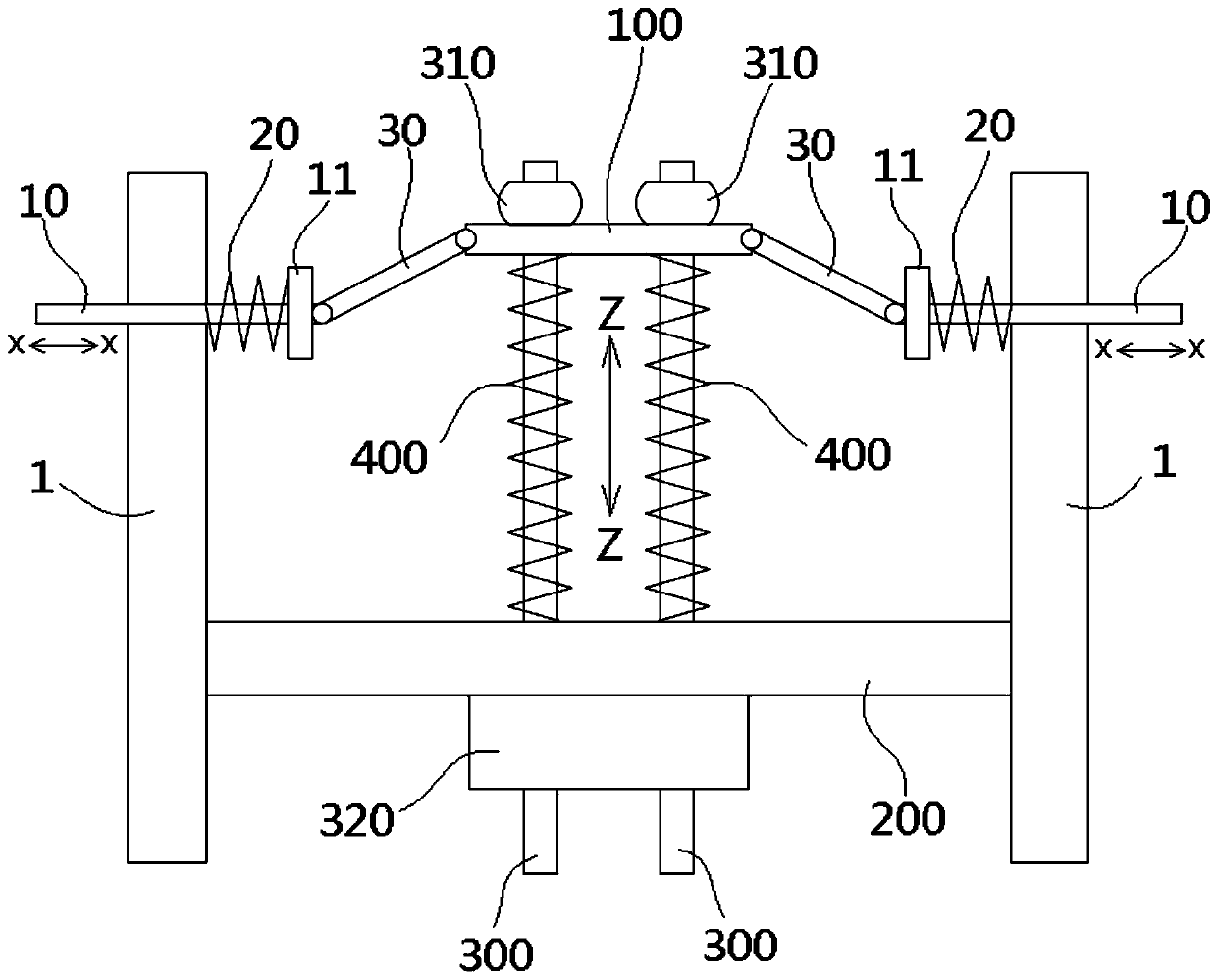
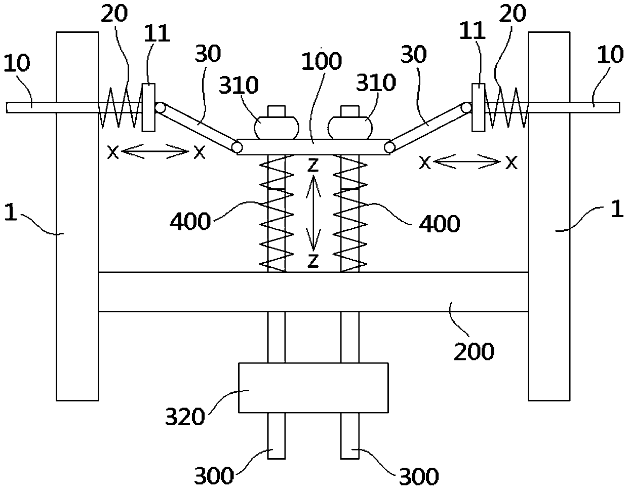
The invention discloses a lift rope head damping device. The lift rope head damping device comprises a pair of vertical support plates, a rope head plate located between the pair of support plates andfixed to the pair of support plates, rope head rods which penetrate through the rope head plate and are used for being connected with a hoist rope of a lift and a rope head springs which are arrangedon the rope head rods in a sleeving manner and supported by the rope head plate. The lift rope head damping device further comprises a rope head cover plate and multiple elastic connection assemblies. One end of each rope head rod is fixed to the rope head cover plate. The rope head springs are compressed between the rope head cover plate and the rope head plate. The elastic connection assembliesare used for enabling the two sides of the rope head cover plate to be elastically connected to the support plates in a vertically movable manner, so that the rope head cover plate is elastically clamped between the pair of support frames and can move vertically. In this way, the dynamic stiffness of the rope head appropriates to zero when the lift operates, the first order natural frequency of alift system is greatly lowered, and the noise lowering and vibration isolating effects on the lift are improved.

Description

Technical field [0001] The invention relates to an elevator rope end vibration damping device. Background technique [0002] In the prior art, the rope end vibration damping device of an elevator traction rope usually includes a rope end rod, a rope end plate and a rope end spring. The rope end plate is fixed to the bracket. The rope rod passes through the rope head plate. The rope head spring is sleeved on the rope head rod and compressed between the rope head plate and the head of one end of the rope head rod. The rope end of the traction rope is connected to the other end of the rope end rod through a dedicated connector. [0003] However, the existing rope head vibration damping device has poor vibration isolation efficiency, and the rope head has a relatively large dynamic stiffness during elevator operation. This will increase the first-order natural frequency of the elevator system and increase the transmission efficiency of vibration energy. Therefore, the current Some ...

Claims


Application Information

Patent Timeline
IPC IPC(8): B66B7/06F16F15/067
CPCB66B7/06F16F15/067
Inventor 解传浩刘浩
Owner SCHINDLER CHINA ELEVATOR CO LTD
Why Eureka
Try Eureka