Reinforcing device for fire-resistant air pipe for nuclear power and fire-resistant air pipe

A reinforcement device and fire-resistant technology, applied in the field of nuclear power plant safety, can solve problems such as difficult support, concave or bent fireproof board 1', crack collapse of fireproof board 1', etc., to ensure integrity, ensure stability, and improve overall the effect of strength

Active Publication Date: 2020-01-24
SUZHOU NUCLEAR POWER RES INST +2
View PDF5 Cites 1 Cited by
  • Summary
  • Abstract
  • Description
  • Claims
  • Application Information

AI Technical Summary

Problems solved by technology

Since the upper fireproof board 1' is only supported by the fireproof boards 1' on both sides, when one side of the upper fireproof board 1' is longer, it is difficult for the fireproof boards 1' on both sides to effectively support the upper part. If there is no effective support inside the air duct, the upper fire-resistant board 1' is easily sunken or bent in the middle due to its own gravity, resulting in weakened overall strength of the upper fire-resistant air duct
In addition, the pressure inside the fire-resistant air duct is fluctuating in an unsteady state, which intensifies the risk of cracks or even collapse in the middle position of the upper fire-proof board 1', which will further weaken the strength of the fire-resistant air duct after long-term operation

Method used


Image

  • Reinforcing device for fire-resistant air pipe for nuclear power and fire-resistant air pipe
  • Reinforcing device for fire-resistant air pipe for nuclear power and fire-resistant air pipe
  • Reinforcing device for fire-resistant air pipe for nuclear power and fire-resistant air pipe

Examples


Embodiment 1

[0027] This implementation example provides a reinforcement device 100 for a fire-resistant air duct for nuclear power.

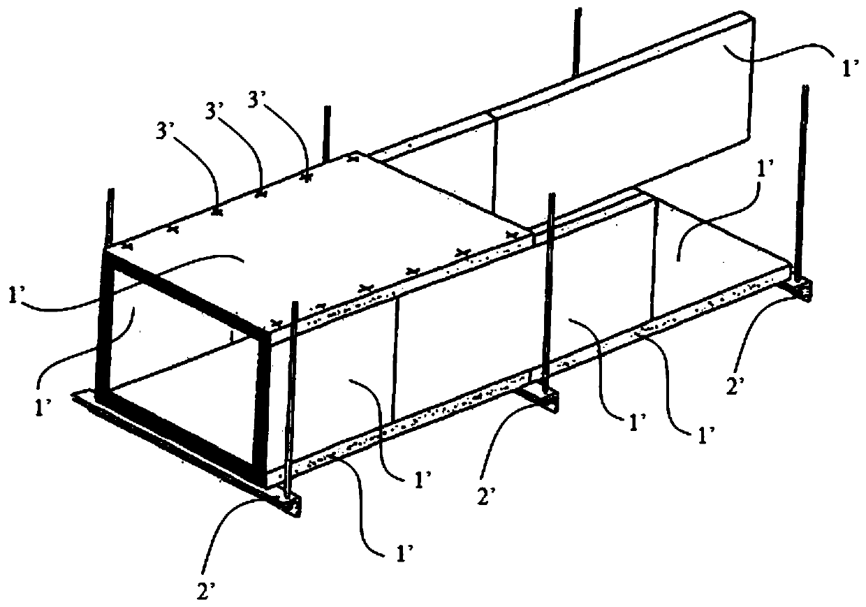
[0028] The first thing to explain is that the fire-resistant air ducts involved in this implementation example are widely used in the important ventilation systems of nuclear power plants. At present, many domestic PWR nuclear power plants have fire-resistant air ducts of this material. According to on-site observation, this kind of PROMATECT-L500 large-section fire-resistant air duct is prone to cracks and collapse defects in the absence of internal reinforcement. The reinforcement device 100 provided in this implementation example can optimize this defect, so that the fire-resistant air duct can be effectively supported, the strength of the fire-resistant air duct can be guaranteed, and the integrity of the important ventilation system of the nuclear island can be ensured.

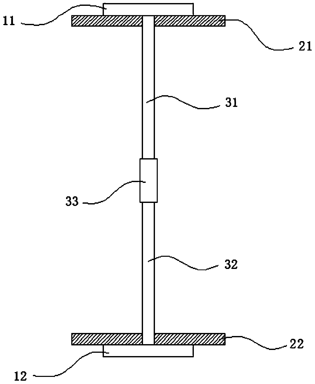
[0029] see figure 2 and image 3 , the reinforcing device 100 includes an uppe...

Embodiment 2

[0042] This implementation example provides a fire-resistant air duct 400 .

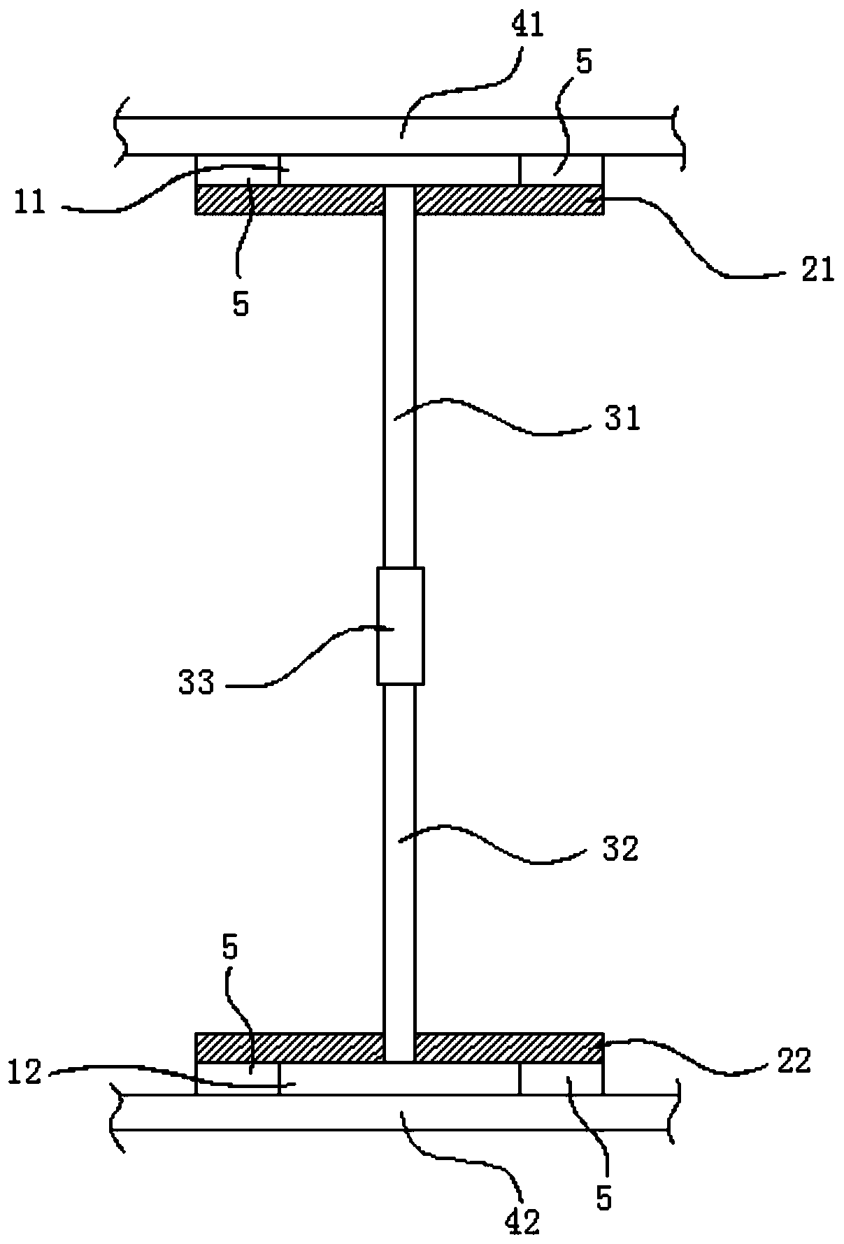
[0043] The fire-resistant air duct 400 includes a top wall (not shown), a bottom wall 42 and two side walls 43 connected between the top wall (not shown) and the bottom wall 42 , wherein the fire-resistant Multiple reinforcement devices 100 provided in Embodiment 1 are installed between the top wall (not shown) and the bottom wall 42 of the air duct 400 .

[0044] In this example, see Figure 4 , the length of the top wall (not shown) of the fire-resistant air duct 400 is 1200-2000 mm, and the fire-resistant air duct 400 has a row of reinforcing devices 100 arranged at equal intervals along the length direction, and two adjacent The spacing between the reinforcing devices 100 is less than or equal to 600mm.

[0045] In this embodiment, the fire-resistant air duct 400 has a better overall strength due to the installation of a row of reinforcement devices 100 between the top wall 41 and the bottom wa...

Embodiment 3

[0047] This implementation example provides a fire-resistant air duct.

[0048] The fire-resistant air duct includes a top wall, a bottom wall and two side walls connected between the top wall and the bottom wall, wherein a plurality of fire-resistant air ducts are installed between the top wall and the bottom wall The reinforcement device provided by Embodiment 1.

[0049] In this embodiment, the length of the top wall of the fire-resistant air duct is 2000-3000 mm, and there are two rows of reinforcement devices arranged at equal intervals along the length direction inside the fire-resistant air duct. The interval between the reinforcement devices is less than or equal to 600mm.

[0050] In this embodiment, two rows of reinforcing devices are installed between the top wall and the bottom wall of the fire-resistant air duct, so that the fire-resistant air duct has better overall strength, which can ensure the integrity of the important ventilation system of the nuclear islan...


PUM


Abstract

The invention discloses a reinforcing device for a fire-resistant air pipe for nuclear power and a fire-resistant air pipe. The reinforcing device comprises an upper top plate, a lower top plate, an upper supporting rod, a lower supporting rod, an intermediate connecting rod, an upper mounting plate and a lower mounting plate; the upper end of the upper supporting rod is connected with the upper top plate, and the lower end of the upper supporting rod penetrates through the upper mounting plate and is connected with the upper end of the intermediate connecting rod in an adjustable mode; the lower end of the lower supporting rod is connected with the lower top plate, and the upper end of the lower supporting rod penetrates through the lower mounting plate and is connected with the lower endof the intermediate connecting rod in an adjustable mode; the size of the upper mounting plate in at least one dimension is larger than the size of the upper top plate in the corresponding dimension;the size of the lower mounting plate in at least one dimension is larger than the size of the lower top plate in the corresponding dimension; the upper top plate and the lower top plate abut againstthe top wall and the bottom wall in the fire-resistant air pipe correspondingly; and the upper mounting plate and the lower mounting plate are correspondingly fixed with the top wall and the bottom wall in the fire-resistant air pipe. According to the reinforcing device, the fire-resistant air pipe is effectively supported, the strength of the fire-resistant air pipe is strengthened, and the integrity of a ventilation system is ensured.

Description

technical field [0001] The invention relates to the technical field of nuclear power plant safety, in particular to the technical field of fire-resistant air ducts for nuclear power, and relates to a reinforcement device for fire-resistant air ducts for nuclear power and a fire-resistant air duct. Background technique [0002] At present, a fire-resistant air duct made of calcium carbonate is usually used in the ventilation system of the nuclear island of the domestic PWR nuclear power plant (such as DVC, DVE, DVG, DVH, etc.). The fire-resistant air duct has a certain fire resistance due to the material itself, so as to ensure that the ventilation system can remain intact within a certain fire time. This fire-resistant air duct is made of PROMATECT-L500 single-layer fireproof board 1', using "PROMACOL S" glue for joint sealing, and metal horse nails 3' for assembly (see figure 1 , figure 1 shows the structure of the refractory air duct). Wherein, the lower fireproof board...

Claims


Application Information

Patent Timeline
Patent Type & Authority Applications(China)
IPC IPC(8): F16L9/08
CPCF16L9/003F16L9/085
Inventor 金聪苏林白金川
Owner SUZHOU NUCLEAR POWER RES INST
Why Eureka
Try Eureka