
Air fan automatic oil filling device and air fan

An automatic oil injection and fan technology, which is applied to machines/engines, components of pumping devices for elastic fluids, mechanical equipment, etc., can solve problems such as difficult lubrication of bearings in fans, reduce manual operations, and be widely used. cost saving effect

Pending Publication Date: 2020-01-24
CHINA RAILWAY SIYUAN SURVEY & DESIGN GRP
View PDF0 Cites 2 Cited by
  • Summary
  • Abstract
  • Description
  • Claims
  • Application Information

AI Technical Summary

Problems solved by technology

[0003] The purpose of the present invention is to overcome the problem of difficult lubrication of fan inner bearings in the prior art

Method used


Image

  • Air fan automatic oil filling device and air fan
  • Air fan automatic oil filling device and air fan
  • Air fan automatic oil filling device and air fan

Examples


Embodiment 1

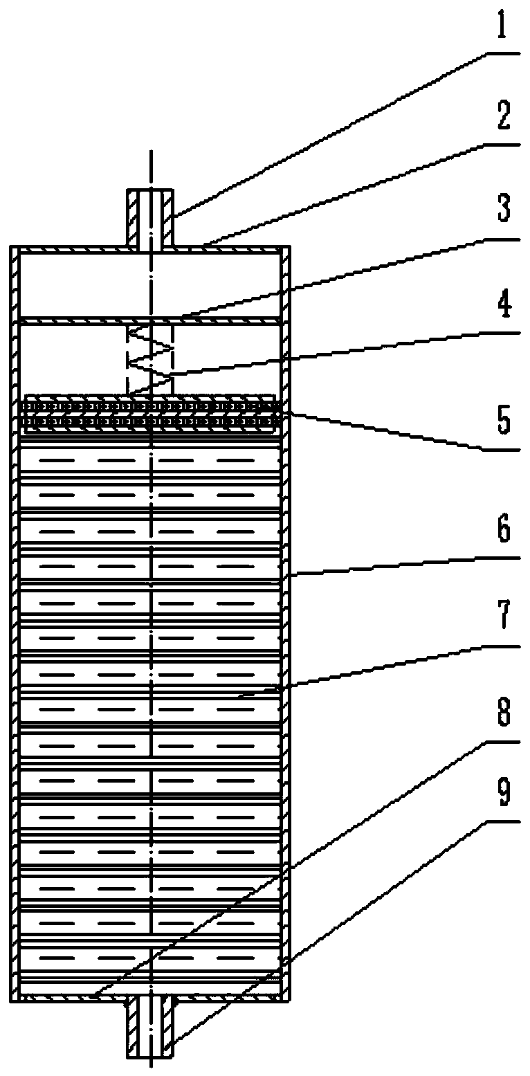
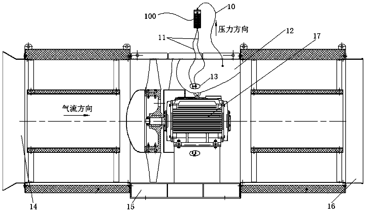
[0026] Such as figure 1 As shown, the present invention provides an automatic oiling device for a fan, which includes an oil storage cylinder 6 with openings at both ends. It communicates with the lubricating place through an oil pipe 11; the oil storage cylinder 6 stores a lubricant 7. It can be seen that the automatic oiling device 100 for the blower fan 15 includes an oil storage cylinder 6 with openings at both ends. The oil pipes 11 communicate with each other; the oil storage cylinder 6 stores a lubricant 7 . During the operation of the fan 15, static pressure is generated on the back of the fan to form a static pressure space on the back of the fan 15, which is connected to the oil storage cylinder 6 through the air pipe 10, and the lubricant 7 is stored in the oil storage cylinder 6. Under the action of pressure, the lubrication Agent 7 is slowly squeezed into the lubricated place. Lubricating place comprises motor 17 bearing 18, and lubricant 7 is generally grease,...

Embodiment 2

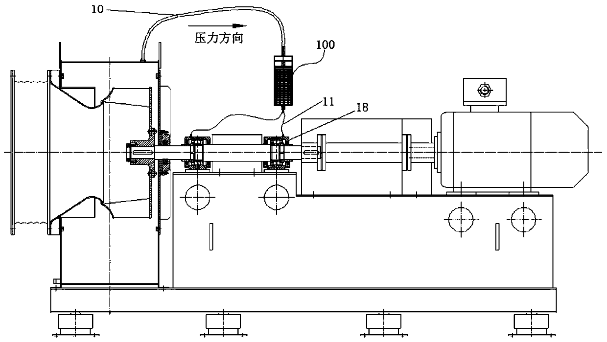
[0035] Such as figure 2 with image 3 As shown, the automatic oiling device 100 is fixedly connected to the casing of the fan 15 , and the automatic oiling device 100 is installed near the static pressure space 12 on the back of the fan, and is located between the air inlet pipe 14 and the air outlet pipe 16 . When the fan 15 is running, it can provide potential energy to the oil injection device, so as to supply oil to the bearing 18 in the motor 17 .

[0036] The specific working principle is as follows Figure 1 to Figure 3 Shown:

[0037] The automatic oiling device 100 is connected to the casing of the fan 15 , and the fan 15 can provide potential energy to be supplied to the oil storage cylinder 6 of the automatic oiling device 100 when it is running. The oil joint 9 of the automatic oiling device 100 is connected to a lubricating point, which can be lubricated at a single point or at multiple points. The intake end of the oil storage cylinder 6 is slidably provided...


PUM


Abstract

The invention belongs to the technical field of air fan lubrication and particularly provides an air fan automatic oil filling device and an air fan. The air fan automatic oil filling device comprisesan oil storage barrel with the two ends being open, the air inlet end of the oil storage barrel communicates with an air fan back face static pressure space through an air pipe, the oil outlet end ofthe oil storage barrel communicates with lubrication positions through oil pipes, the oil storage barrel is internally stored with a lubricant, one end of the oil storage barrel stored with the lubricant is connected with the air fan, air fan static pressure is utilized as a power source, and automatic oil filling of the air fan and an air fan motor can be realized under the air fan start operation, static shutdown and other various working conditions correspondingly. Compared with a traditional oil filling method of manual oil filling gun operations, the amount of manual operations is greatly reduced, and the air fan automatic oil filling device and the air fan have the advantages of being convenient and flexible to install, safe and reliable and capable of saving cost and are widely used in the air fans of tunnels, buildings and other engineering projects.

Description

technical field [0001] The invention belongs to the technical field of fan lubrication, and in particular relates to an automatic oiling device for a fan and the fan. Background technique [0002] With the development of the national economy, the consumption of fans has increased rapidly, and each fan basically needs to use a motor or a transmission unit. The bearings of each motor or transmission unit need regular maintenance and maintenance. In the use of most fans, the method of adding lubricant is to manually inspect the oil gun by the staff, which will continue to increase equipment operation and maintenance. Labor costs during the period, and the environment where some equipment is located during the operation period has adverse factors such as noise and vibration. Frequent manual refueling operations will have an adverse impact on the health of the staff. Contents of the invention [0003] The purpose of the invention is to overcome the problem of difficult lubrica...

Claims


Application Information

Patent Timeline
Patent Type & Authority Applications(China)
IPC IPC(8): F16N11/08F16N13/02F04D29/063
CPCF04D29/063F16N11/08F16N13/02
Inventor 蔡崇庆车轮飞付维纲林昶隆胡清华夏继豪刘宇圣陈玉远刘俊甘甜刘健王小飞陈慧冯腾夏爱凤
Owner CHINA RAILWAY SIYUAN SURVEY & DESIGN GRP
Learn More