A fuel dispenser with a gas spring tube body

The technology of a spring tube and a fuel dispenser is applied to the fuel dispenser field of the fuel dispenser and the gas spring tube body, which can solve problems such as lack of practicability, and achieve the effects of improving practicability, improving accuracy and high work efficiency.

Active Publication Date: 2016-01-20
ZHEJIANG ZHENGXING FITNESS
View PDF4 Cites 0 Cited by
  • Summary
  • Abstract
  • Description
  • Claims
  • Application Information

AI Technical Summary

Problems solved by technology

At present, the refueling of gas springs is manually refueled by workers, which lacks practicability

Method used


Image

  • A fuel dispenser with a gas spring tube body
  • A fuel dispenser with a gas spring tube body
  • A fuel dispenser with a gas spring tube body

Examples


Embodiment Construction

[0028]The following are specific embodiments of the present invention and in conjunction with the accompanying drawings, the technical solutions of the present invention are further described, but the present invention is not limited to these embodiments.

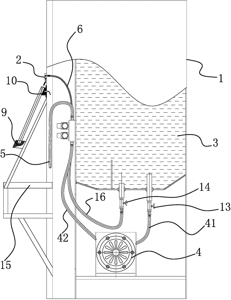
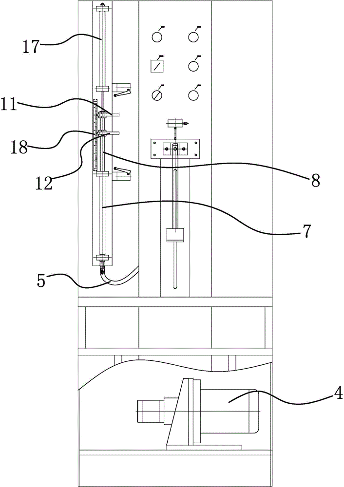
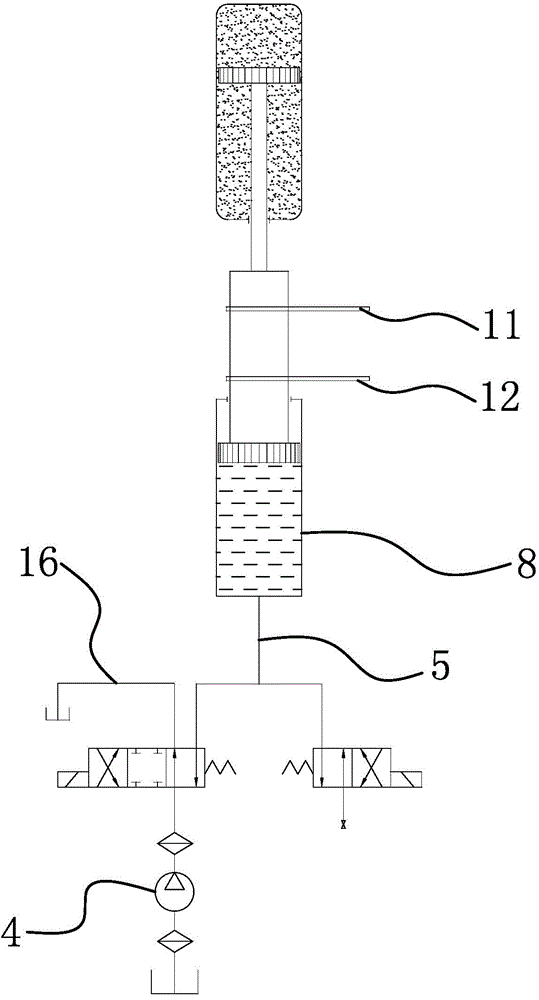
[0029] Such as figure 1 and figure 2 As shown, a fuel dispenser for a gas spring tube body includes a chassis 1, the outer wall of the cabinet 1 is provided with a positioning structure capable of detachably positioning the gas spring tube body, and the outer side wall of the cabinet 1 is also provided with a positioning structure. There is an oil outlet 2, and the oil that goes out from the oil outlet of the oil outlet 2 can enter the gas spring tube body, and an oil storage tank 3 is also arranged in the described chassis 1, and the inlet of the oil storage tank 3 and the oil outlet 2 A conveying device is provided between the oil ports; the conveying device includes an oil pump 4, an oil injection pipe 5, a fuel pipe 6...


PUM


Abstract

The invention provides an oiling machine of a gas spring pipe. The oiling machine solves the technical problems that an existing oiling machine is low in oiling efficiency, poor in oiling accuracy and the like. The oiling machine of the gas spring pipe comprises a case, wherein the outer side wall of the case is provided with a locating structure which can detachably locate a gas spring pipe body, the outer side wall of the case is further provided with an oil outlet nozzle, oil flowing out of an oil outlet of the oil outlet nozzle can enter the gas spring pipe body, an oil storage box is further arranged in the case, and a conveying device is arranged between the oil storage box and an oil inlet of the oil outlet nozzle. The oiling machine has the advantages of being high in oiling efficiency, good in oiling accuracy and the like.

Description

technical field [0001] The invention belongs to the technical field of machinery, and relates to a fuel dispenser, in particular to a fuel dispenser with a gas spring tube body. Background technique [0002] Gas spring is an industrial accessory that can perform functions such as support, buffer, brake, height adjustment and angle adjustment. It consists of the following parts: pressure cylinder, piston rod, piston, sealing guide sleeve, filler (inert gas or oil-gas mixture), control components in the cylinder and control components outside the cylinder refer to controllable gas springs and joints, etc. The principle is to fill the closed pressure cylinder with an inert gas or an oil-gas mixture, so that the pressure in the cavity is several times or dozens of times higher than the atmospheric pressure, and the pressure difference generated by the cross-sectional area of ​​the piston rod is smaller than that of the piston. To realize the movement of the piston rod. Due to ...

Claims


Application Information

Patent Timeline
Patent Type & Authority Patents(China)
IPC IPC(8): B67D7/04B67D7/30
Inventor 董旭
Owner ZHEJIANG ZHENGXING FITNESS
Why Eureka
Try Eureka