a sensor
A sensor and pressure sensing technology, applied in the field of sensors, can solve problems such as noise and other environmental factors that cannot be effectively eliminated, and achieve the effect of reducing the signal
- Summary
- Abstract
- Description
- Claims
- Application Information
AI Technical Summary
Problems solved by technology
Method used
Image
Examples
Embodiment 1
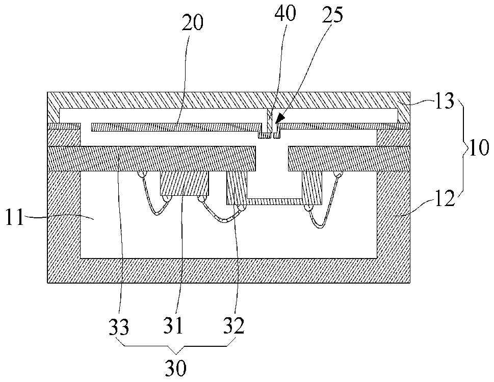
[0053] figure 1 A schematic structural diagram of the sensor provided in Example 1.
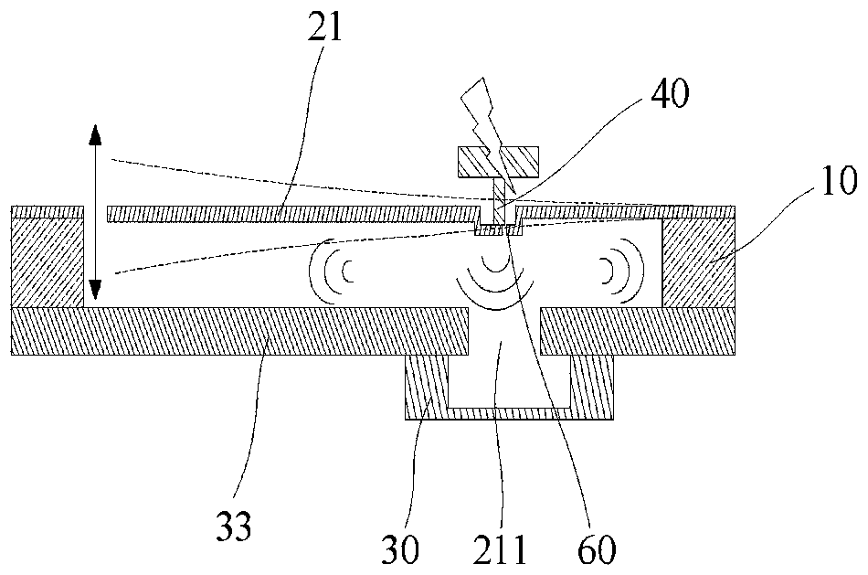
[0054] figure 2 A schematic diagram of the working principle of the sensor provided in Embodiment 1.
[0055] see figure 1 with figure 2 , the pressure sensing component 30 is set separately from the pressure generating unit 20, the pressure generating unit 20 is preferably a flexible structure 21, one end of which is extended and connected to the inner wall of the housing 10, and the other end is a cantilever end, the pressure generating unit 20 is a cantilever The conduction strut 40 is connected between the outer cover 13 of the casing 10 and the pressure generating unit 20 .
[0056] The double arrow line in the figure indicates that the flexible structure 21 can vibrate up and down, and the dotted line indicates the range of the flexible structure 21 vibrating up and down.
[0057] see figure 2 , in this embodiment, when the external signal to be measured, such as external vibra...
Embodiment 2
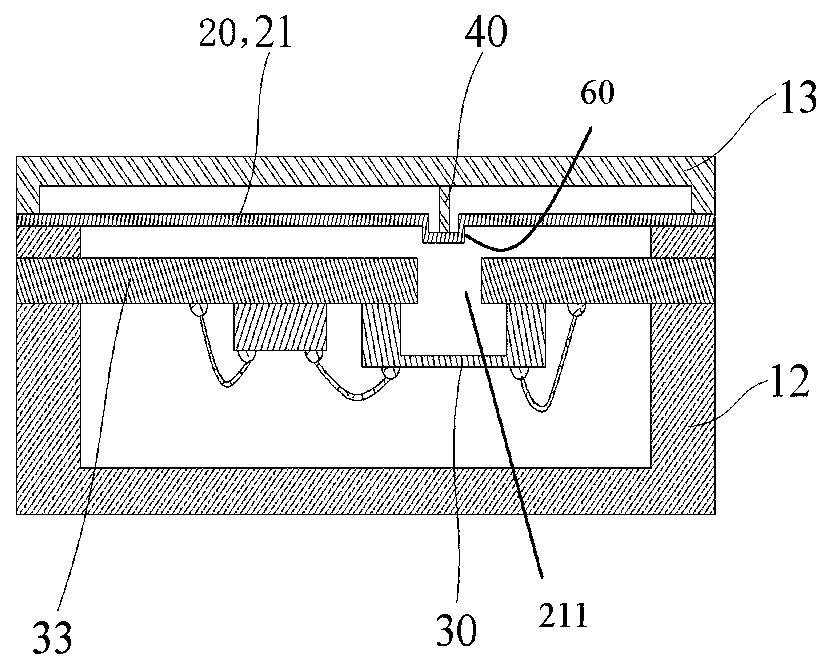
[0059] image 3 Schematic diagram of the structure of the sensor provided in Example 2.
[0060] see image 3 As shown, the difference between Embodiment 2 and Embodiment 1 is that both ends of the pressure generating unit 20 such as the flexible structure 21 are extended and connected to the inner wall of the housing 10. In this embodiment, the external signal to be measured passes through the housing 10 and the conduction strut 40 are transmitted to the pressure generating unit 20, the pressure generating unit 20 thus produces reciprocating motion, causing the surrounding medium of the pressure generating unit 20 such as air disturbance, the disturbance concentrator 60 concentrates the change of the air disturbance around the pressure sensing component 30, and then The pressure change is received by the pressure sensing component 30 .
Embodiment 3
[0062] Figure 4 Schematic diagram of the structure of the sensor provided in Example 3.
[0063] Figure 5 for Figure 4 Schematic diagram of the structure of the pressure generating unit of the sensor shown.
[0064] see Figure 4 with Figure 5 The difference between the third embodiment and the second embodiment is that the structure of the pressure generating unit 20 is different. The pressure generating unit 20 includes a mounting portion 22 disposed in the accommodating cavity 11, two fixing portions 23 both connected to the inner side wall of the housing 10, and at least two elastically connected to the two fixing portions 23 and the The elastic connection part 24 between the installation parts 22 , the disturbance concentrator 60 is disposed on the installation part 22 , and the conductive strut 40 abuts on the installation part 22 .
[0065] The pressure sensing assembly 30 of the first to third embodiments described above is provided separately from the pressu...
PUM
 Abstract
Description
Claims
Application Information
 - R&D
- Intellectual Property
- Life Sciences
- Materials
- Tech Scout
- Unparalleled Data Quality
- Higher Quality Content
- 60% Fewer Hallucinations
Browse by: Latest US Patents, China's latest patents, Technical Efficacy Thesaurus, Application Domain, Technology Topic, Popular Technical Reports.
© 2025 PatSnap. All rights reserved.Legal|Privacy policy|Modern Slavery Act Transparency Statement|Sitemap|About US| Contact US: help@patsnap.com


