
Hydraulic pipe bender

A pipe bender and hydraulic technology, which is applied in the field of hydraulic pipe benders, can solve the problems of low safety reliability and low pipe bending processing efficiency, and achieve the effects of meeting safe use requirements, saving raw materials, and improving processing efficiency

Active Publication Date: 2021-05-04
ZHEJIANG VALUE MECHANICAL & ELECTRICAL PROD CO LTD
View PDF8 Cites 0 Cited by
  • Summary
  • Abstract
  • Description
  • Claims
  • Application Information

AI Technical Summary

Problems solved by technology

[0003] The present invention mainly provides a kind of pipe bending processing that can meet various specifications without changing the rotating die, and the bending processing saves time and labor, and is safe and reliable hydraulic pipe bender, which solves the problems existing in the prior art. A set of bending dies and rotating dies can only process pipes of one specification. When changing the pipe diameter, the bending dies and rotating dies need to be replaced accordingly. The processing efficiency of bending pipes is low, and the safety and reliability are low.

Method used


Image

  • Hydraulic pipe bender
  • Hydraulic pipe bender
  • Hydraulic pipe bender

Examples


Embodiment

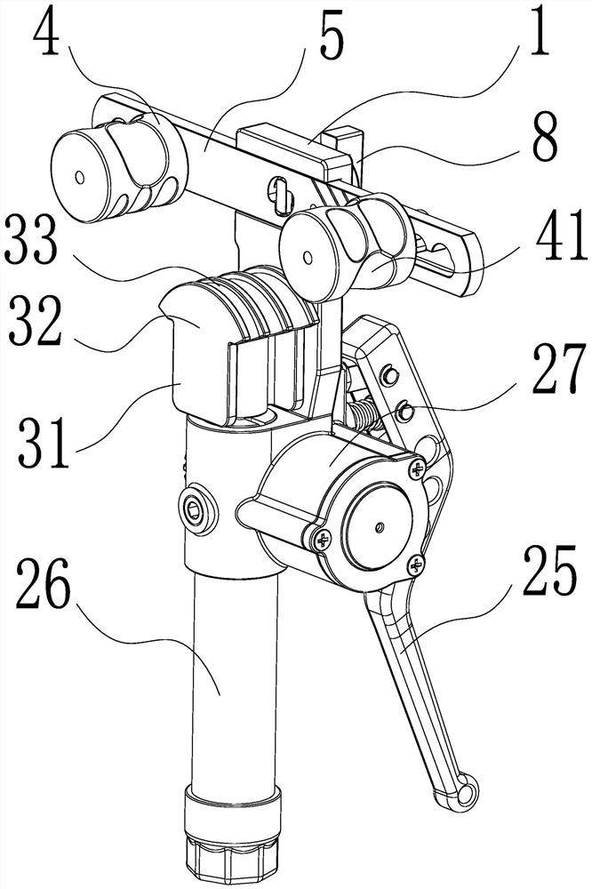
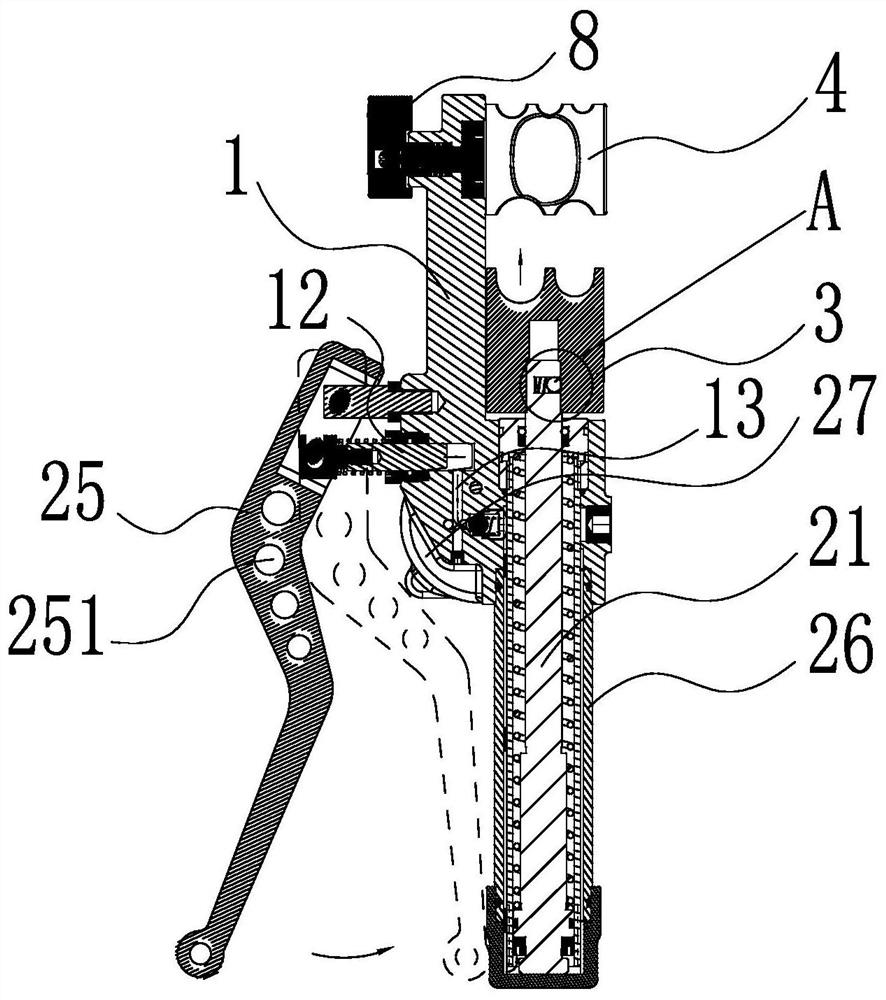
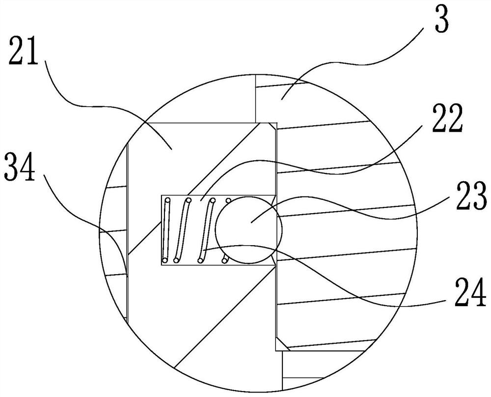
[0029] Such as figure 1 with figure 2 As shown, a hydraulic pipe bender of the present invention includes a body 1 and a hydraulic mechanism located on the body 1. The hydraulic mechanism includes an oil cylinder 26 fixed at the lower end of the body 1. The opening of the oil cylinder 26 faces upward, and the opening of the oil cylinder 26 The push rod 21 is interfitted and plugged in, and the top of the push rod 21 extends outside the opening of the oil cylinder 26, and an oil storage cylinder 27 and a hydraulic handle 25 are also installed on the outer ring surface of the body 1 near the opening of the oil cylinder 26, and the oil storage cylinder 27 passes through the oil inlet The oil circuit 13 and the oil return circuit are connected with the oil cylinder 26, and the connection end of the hydraulic handle 25 is connected to the body 1 in rotation, and the free end of the hydraulic handle 25 extends downward along the shape of the body 1, and a Several lightening holes ...


PUM


Abstract

The invention discloses a hydraulic pipe bender, which provides a safe and reliable hydraulic pipe bender that can meet various specifications of pipe bending processing without changing the rotary die, saves time and labor, and solves the problem There are technical problems such as a set of bending dies and rotary dies that can only process pipes of one specification, low processing efficiency of bending pipes, and low safety and reliability. It includes the body and the hydraulic mechanism on the body. The hydraulic handle pushes the push rod upward through hydraulic oil, and the bending die is detachably connected to the top of the push rod. There is a lower guide groove on the top outer ring surface of the bending die that is compatible with the pipe to be processed. The two sides on the opposite side of the machine body are respectively connected to the rotary mold. The outer ring surface of the rotary mold forms several rolling areas along the circumferential direction. At least one type of pinching groove is provided on each rolling area. Together with the lower guide groove, the pipe to be processed of the corresponding specification is clamped for pipe bending processing.

Description

technical field [0001] The invention relates to a hydraulic pipe bender, in particular to a hydraulic pipe bender capable of processing pipes of various specifications without changing bending dies. Background technique [0002] The hydraulic pipe bender is a pipeline tool that uses the handle to press the ejector rod to compress the hydraulic oil, and is driven by the hydraulic system to press the pipe bending die to complete the pipe bending. There is usually only one arc groove on the bending die and rotary die of the existing hydraulic pipe bender for pipe bending processing. During the pipe bending process, it is necessary to replace the bending die and rotary die of the corresponding specifications to realize the pipe bending process, which not only takes time and effort, but also leads to low efficiency of the pipe bending process, and in some special occasions, such as working at heights, it is very easy to cause safety accidents. At the same time, frequent replacem...

Claims


Application Information

Patent Timeline
Patent Type & Authority Patents(China)
IPC IPC(8): B21D7/06
CPCB21D7/063
Inventor 蒋友荣
Owner ZHEJIANG VALUE MECHANICAL & ELECTRICAL PROD CO LTD
Learn More