Auxiliary transmission device, capable of being adjusted on line, for float glass annealing kiln
An auxiliary transmission, float glass technology, applied in glass manufacturing equipment, glass transportation equipment, manufacturing tools and other directions, can solve the problems of inconvenient online adjustment, manual operation, high temperature, achieve safety and ease, reduce labor intensity, block Effects of temperature radiation and dust
- Summary
- Abstract
- Description
- Claims
- Application Information
AI Technical Summary
Problems solved by technology
Method used
Image
Examples
Embodiment 1
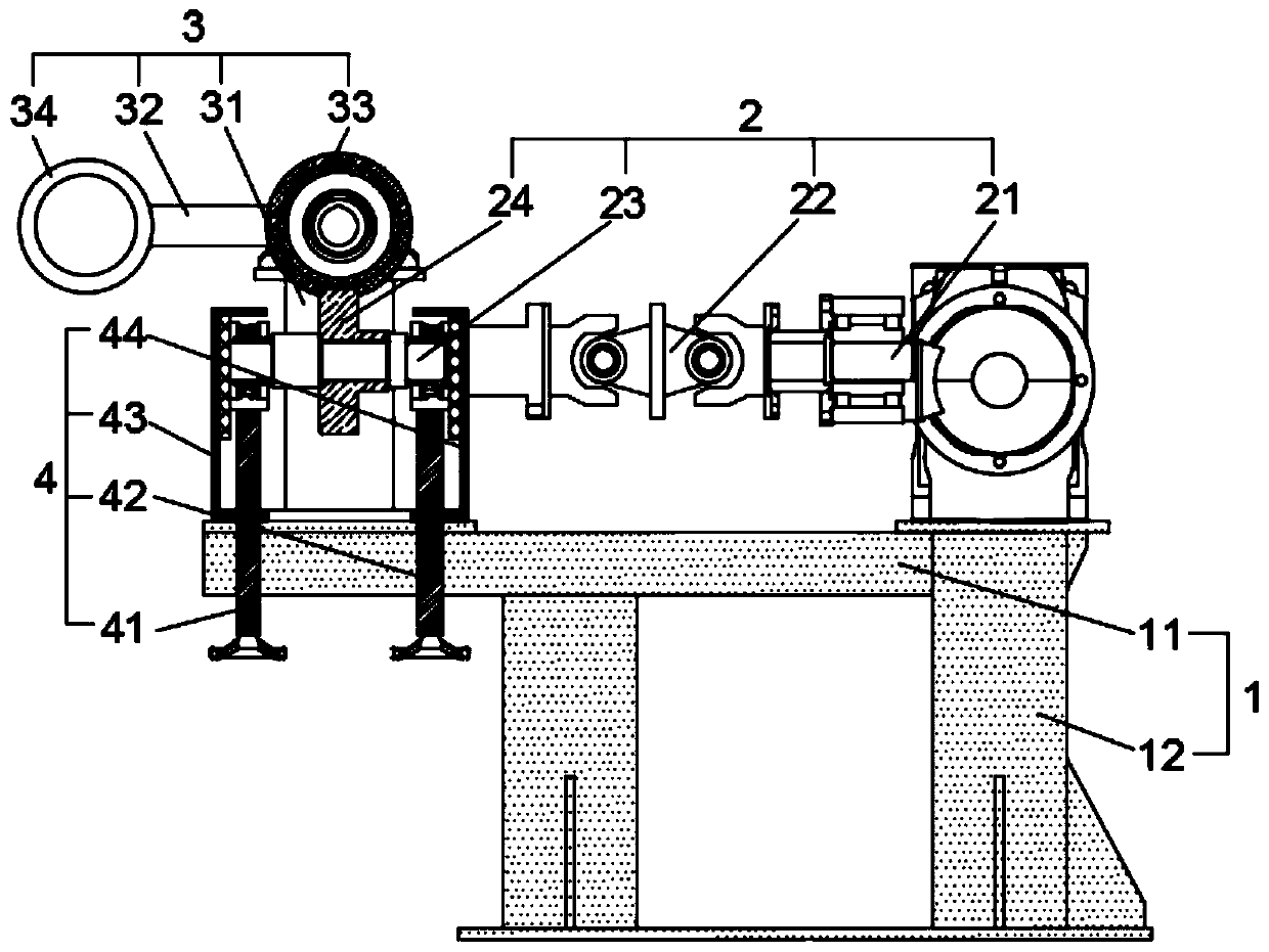
[0036] Such as figure 1As shown, this embodiment discloses an auxiliary transmission device that can be adjusted online for a float glass annealing kiln, specifically figure 1 For reference, it includes the frame 1, the active transmission mechanism 2, the auxiliary transmission mechanism 3 and the height adjustment device 4; the height adjustment device 4 is fixed on the frame 1 to adjust the main shaft transmission mechanism 2 to its gear and auxiliary transmission Mechanism 3 gears carry out meshing transmission.
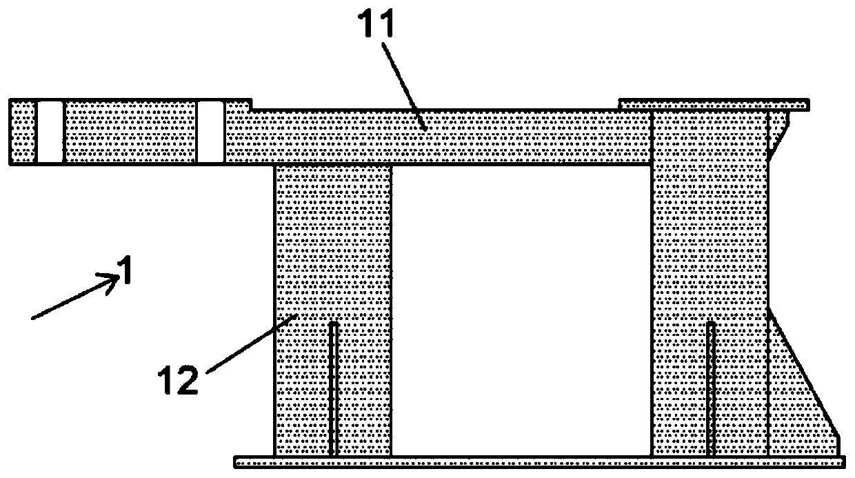
[0037] Such as figure 2 As shown, the frame 1 includes a horizontal support plate 11 and legs 12. The horizontal plane of the horizontal support plate 11 includes a connection area and a non-connection area. internally threaded holes.
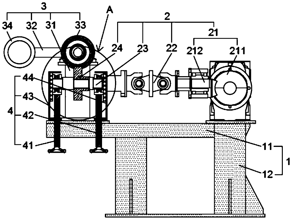
[0038] Such as image 3 , Figure 4 As shown, the active transmission mechanism 2 includes a first power assembly 21, a first cardan shaft 22, a connecting shaft 23 and a driving gear 24; the first power assembly 21 is insta...
Embodiment 2
[0048] Such as Figure 4 , Figure 5 As shown, the difference between this embodiment and the first embodiment is that the support device 31 includes a first bracket 311 and a third bearing seat 312; the first bracket 311 is welded on the non-connecting area of the horizontal support plate 11, and can also be installed by bolts On the non-connecting area, the third bearing seat 312 is welded on the top of the first bracket 311, and can also be installed by bolts; one end of the gear shaft of the transmission gear 33 is coaxially connected with the third bearing seat 312, and the other end is connected to the first bracket 312 through a flange. The output shafts of the two power components 32 are connected; the setting of the first bracket 311 can support the transmission gear 33 and the second power component 32 .
[0049] Such as Figure 6 As shown, the supporting device 31 also includes a protective cover 313, the protective cover 313 is a structure with an open side and...
Embodiment 3
[0051] Such as image 3 , Figure 4 , Figure 6 , Figure 7 As shown, the present embodiment is different from Embodiment 1 and Embodiment 2 in that the height adjustment device 4 also includes a second bracket 43 and a third bracket 44; the second bracket 43 and the third bracket 44 are welded on the On the connection area, it can also be fixed by bolts, and the positions of the second bracket 43 and the third bracket 44 correspond to the positions of the first threaded rod 41 and the second threaded rod 42 respectively; the first bearing seat 231, the second bearing Seat 232 is respectively movably connected with second bracket 43 and third bracket 44; through the setting of height adjustment device 4, adjusting height adjustment device 4 makes driving gear 24 mesh with transmission gear 33, which can ensure the safety of installers and is easy to operate.
[0052] The second support 43 is equipped with a first slide rail 431 by a bolt near the third support 44 side, and ...
PUM
 Abstract
Description
Claims
Application Information
 - R&D
- Intellectual Property
- Life Sciences
- Materials
- Tech Scout
- Unparalleled Data Quality
- Higher Quality Content
- 60% Fewer Hallucinations
Browse by: Latest US Patents, China's latest patents, Technical Efficacy Thesaurus, Application Domain, Technology Topic, Popular Technical Reports.
© 2025 PatSnap. All rights reserved.Legal|Privacy policy|Modern Slavery Act Transparency Statement|Sitemap|About US| Contact US: help@patsnap.com


