[0022] The technical solution of the present invention will be described in detail below, but the protection scope of the present invention is not limited to the embodiments.
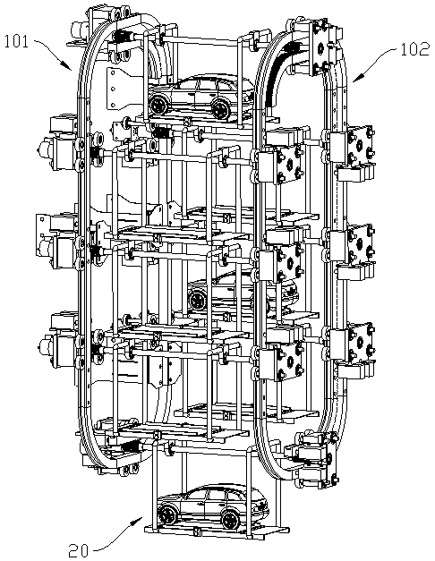
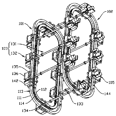
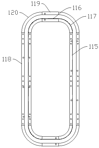
[0023] Such as Figure 1-4 As shown, the three-dimensional parking garage according to the embodiment of the present invention includes a transmission assembly 10 fixed between underground walls and a plurality of rack plates 20. The rack plates 20 are connected to the transmission assembly 10, and the transmission assembly 10 includes a first sliding assembly 101, The second sliding component 102, the connecting component 103, the motor 105 and the electromagnetic lock 142, the first sliding component 101 and the second sliding component 102 are spaced apart, the connecting component 103 connects the first sliding component 101 and the second sliding component 102, the motor 105 is arranged On the connecting assembly 103, as the power output of the driving connecting assembly 103, the electromagnetic lock 142 is arranged on the connecting assembly 103 and is electrically connected to the motor 105. The first sliding assembly 101 and the second sliding assembly 102 are matched with the electromagnetic lock 142. The locking hole 144 is used to position the connecting assembly 103 on the first sliding assembly 101 and the second sliding assembly 102. The first sliding assembly 101 and the second sliding assembly 102 each include an outer guide rail 111 and an inner gear ring 112 that are concentric rings. , The outer guide rail 111 and the inner gear ring 112 are roughly elliptical, the outer side of the outer guide rail 111 and the inner side of the inner gear ring 112 are both provided with a hub 113, and the hub 113 is respectively arranged along the circumference of the outer guide rail 111 and the inner gear ring. A rack 114 is provided on the outer side of 112, and a lock hole 144 is provided on the outer guide rail 111 and the inner gear ring 112. The lock hole 144 is matched with the pin 143 of the electromagnetic lock 142. The inner gear ring 112 includes a detachable long rack 115 , The short rack 116 and the arc rack 117, the long rack 115 and the short rack 116 are connected by the arc rack 117, the long rack 115 and the short rack 116 are connected to the arc rack 117 at the ends A U-shaped groove is provided, and the arc rack 117 has a connecting rod that matches the U-shaped groove. The outer rail 111 includes a long rail 118, a short rail 119 and a circular arc rail 120 that are detachably connected, and the long rail 118 and the short rail 119 are connected by the circular arc rail 120. The connections between the inner ring gear 112 and the outer guide rail 111 are connected and fixed by two pieces of iron and countersunk screws. The connecting assembly 103 is installed on the first sliding assembly 101 and the second sliding assembly 102, and the connecting assembly 103 is in the motor Drive 105 moves along the first sliding assembly 101 and the second sliding assembly 102, thereby driving the rack plate 20 connected to it to move. The connecting assembly 103 includes a connecting shaft 131 and a transmission assembly 132. The connecting shaft 131 is arranged between the first sliding component 101 and the second sliding component 102, and two ends of the connecting shaft 131 are respectively connected with a transmission component 132. The connecting shaft 131 is provided with a bearing 133 for mounting the carrier plate 20 of the carrying vehicle. The carrier plate 20 is suspended between the first sliding assembly 101 and the second sliding assembly 102 through the connecting shaft 131, and the transmission assembly 132 is installed on the first sliding assembly respectively. On the sliding assembly 101 and the second sliding assembly 102, driven by the motor 105, the transmission assembly 132 moves along the first sliding assembly 101 and the second sliding assembly 102, thereby driving the frame plate 20 connected to the connecting shaft 131 to move, and the vehicle Parked in the corresponding position, the transmission assembly 132 includes a gear 134, a guide wheel 135 and a support 136. One end of the gear 134 is connected to the connecting shaft 131, and the other end of the gear 134 is connected to the output shaft of the motor 105 arranged on the support 136. A coupling 137 is provided at the connection between the gear 134 and the output shaft of the motor 105. The output shaft of the motor 105 and the gear 134 of the gear 134 are axially connected through the coupling 137. The gear 134 is held between the outer guide rail 111 and the inner ring gear 112. And meshes with the rack 114. Driven by the motor 105, the gear 134 and the rack 114 meshed with it move relative to each other, and follow the rack 114 on the ring gear 112 along the circumferential direction of the guide rail assembly. During the movement, it drives and The connecting shaft 131 connected to the connecting shaft 131 and the frame plate 20 mounted on the connecting shaft 131 move together, thereby realizing the parking of the vehicle. The guide wheels 135 are arranged in pairs on both sides of the support 136, and the guide wheels 135 respectively cooperate with the outer guide rail 111 and the hub 113 on the inner gear ring 112. This structural design not only has a guiding effect, but also makes it more precise to adjust the vehicle. The entire transmission assembly 132 is clamped and fixed on the guide rail assembly by the guide wheels 135 respectively matched with the outer guide rail 111 and the inner gear ring 112, thereby tightly connecting the entire connecting assembly 103 and the guide rail assembly to form a stable whole The mechanism is firm, safe and reliable. In addition, the support 136 is also provided with a motor 105 and an electromagnetic lock 142. The electromagnetic lock 142 is electrically connected to the motor 105. The support 136 includes a motor support plate 138, a first guide wheel plate 139 and a second The guide wheel plate 140. Combine figure 2 with Figure 4 As shown, the motor support plate 138 is located on the outer side of the first sliding component 101 or the second sliding component 102 away from the connecting shaft 131. A motor 105 is provided on the outer side of the motor support plate 138 away from the first sliding assembly 101 or the second sliding assembly 102, and the output shaft of the motor 105 penetrates the motor support plate 138, and the motor support plate 138 is close to the first sliding assembly 101 or the second sliding assembly The inner side of 102 is provided with a first guide wheel plate 139 and a second guide wheel plate 140, and the ends of the first guide wheel plate 139 and the second guide wheel plate 140 away from the motor support plate 138 are provided with a guide wheel 135. The guide wheel 135 on the guide wheel plate 139 cooperates with the hub 113 on the inner ring gear 112. Since its power comes from the movement of the gear 134 driven by the motor 105, it acts as a driving wheel. The guide wheel 135 on the second guide wheel plate 140 and The hub 113 on the outer guide rail 111 is matched. The guide wheel 135 on the first guide wheel plate 139 rolls along the hub 113 on the outer guide rail 111 as a driven wheel. The support 136 also includes a solenoid valve support plate 141, The solenoid valve support plate 141 is connected to the motor support plate 138, and an electromagnetic lock 142 is provided on the solenoid valve support plate 141. Both the outer guide rail 111 and the inner gear ring 112 are provided with a lock hole 144, and the lock hole 144 is matched with the bolt 143 of the electromagnetic lock 142. The electromagnetic lock 142 is electrically connected to the motor 105, and the electromagnetic lock 142 is controlled by the motor 105 to turn on and off, thereby controlling the expansion and contraction state of the latch 143 of the electromagnetic lock 142. When a shelf plate 20 moves to a suitable position, the motor 105 is powered off. The bolt 143 of the electromagnetic lock 142 is extended and inserted into the lock hole 144 on the outer guide rail 111 and the inner gear ring 112 to realize limited parking.
[0024] When the vehicle is to be retrieved, power is supplied to the motor 105 to make the entire transmission assembly 10 run. At this time, the latch 143 of the electromagnetic lock 142 on the solenoid valve support plate 141 contracts, so that the frame continues to run to the next parking space. In the present invention, the electromagnetic lock 142 is used to position the transmission assembly 132, thereby positioning the shelf plate 20 connected to it, ensuring that the shelf plate 20 is stopped and parked when the shelf plate 20 is moved to a suitable position. The shelf plate 20 is arranged in the first sliding assembly 101 and The second sliding assembly 102 is connected to the connecting assembly 103. The shelf plate 20 includes a parking platform 201 and a suspension plate 202 connected to the parking platform 201. A bolt is provided at the link between the suspension plate 202 and the parking platform 201. The parking platform 201 Corresponding bolt holes are provided; the parking platform 201 is fixed to the bottom of the tray 20 by bolts and nuts. A lifting ring 203 is provided on the top of the suspension plate 202, and the lifting ring 203 is connected with the connecting shaft 131. Specifically, the lifting ring 203 is connected to the bearing 133 on the connecting shaft 131. The suspension disc 202 is connected to the output shaft of the motor 105 through two bearings 133 (of course, there can be more) mounted on the connecting shaft 131, and moves along the guide rail assembly with the transmission assembly 10 to ensure that each parking space is synchronized up and down. Keep level with the ground to prevent vehicles from slipping off. Because the suspension disc 202 and the parking platform 201 of the present invention are both detachably connected, parking spaces can be freely installed and disassembled according to the number of cars that need to be parked. The opposite sides of the parking platform 201 are respectively A boss 204 and a baffle 205 are provided, the boss 204 is connected to the parking platform 201, and the baffle 205 is connected to the boss 204 through a screw mechanism. Through the retractable feature of the screw mechanism, the distance between the baffle plates 205 on both sides of the parking platform 201 can be adjusted, thereby ensuring that the vehicle is parked correctly and making the rack plate 20 evenly stressed. The baffle 205 is located above the top surface of the parking platform 201, and is in a non-contact state with the parking platform 201. The two ends of the parking platform 201 are respectively provided with deceleration belts 206 to further ensure parking safety.
[0025] The shelf 20 also includes a detection device. The detection device includes a controller communicatively connected with the motor 105 and a sensor communicatively connected with the controller. The sensor detects whether there is a vehicle on the shelf 20 to determine whether it is an empty parking space, and transmits the detection signal to The controller, after receiving the signal, makes corresponding control. For example, when the detected shelf 20 is empty, the controller records the parking space number of the shelf 20, and when parking is required, the shelf number of the parking space The tray 20 is placed at the parking entrance at the bottom of the garage, ready to park. When there are multiple empty parking spaces, the one with the frontmost moving direction can be selected and parked at the parking entrance, and the idle trays 20 at the back line up in order to wait for parking; When the detected frame plate 20 carries a vehicle, move the vehicle with the parking space number to the middle or upper part of the garage, and then move it to the parking lot when the owner picks up the vehicle. The sensor is a proximity sensor, preferably a photoelectric pair Shooting type, inductive type, Hall type, capacitive type, but not limited to the above types.
[0026] When the car owner stops, park the car on the parking platform 201 from the parking entrance and exit at the bottom of the parking garage and write down the number (parking space number). When the owner leaves, the tray 20 is driven by the motor 105 to rotate, and all motors 105 Drive all the trays 20 to move up and down in an orderly manner, transfer the parked cars to the upper part of the parking lot, and transfer the empty trays 20 to the entrance and exit position, waiting for the next parking vehicle owner to stop. When the rack plate 20 hears the corresponding position, the motor 105 is powered off, and the pin 143 of the electromagnetic lock 142 extends into the corresponding lock hole 144 on the outer guide rail 111 and the inner gear ring 112 for positioning. When the car owner picks up the car, the car can be retrieved by means of the car number. The motor 105 is energized and the latch 143 of the electromagnetic lock 142 is retracted. The motor 105 drives the rack plate 20 to move, and transmits the rack plate 20 of the corresponding parking number to the At the entrance and exit, the owner can take out the corresponding car.
[0027] Finally, it should be noted that the above are only the preferred embodiments of the present invention and are not intended to limit the present invention. Although the present invention has been described in detail with reference to the foregoing embodiments, it is still for those skilled in the art. The technical solutions recorded in the foregoing embodiments may be modified, or some of the technical features may be equivalently replaced. Any modification, equivalent replacement, improvement, etc., made within the spirit and principle of the present invention shall be included in this Within the scope of protection of the invention.