
Emission generation test device

A test device and emission technology, applied in the field of emission generation test devices, can solve the problems of acquisition, unfavorable test rules, and inability to accurately control the concentration of components.

Inactive Publication Date: 2020-01-31
CSSC POWER INST CO LTD
View PDF12 Cites 0 Cited by
  • Summary
  • Abstract
  • Description
  • Claims
  • Application Information

AI Technical Summary

Problems solved by technology

[0004] However, due to the influence of the engine load point, even if the other test conditions remain unchanged, the component concentrations of sulfur oxides and nitrogen oxides in the exhaust often cannot remain stable, and there will be certain fluctuations
Therefore, it is impossible to precisely control the component concentration of the discharge, which is not conducive to the acquisition of test rules. Often a large number of tests are required to obtain the complete performance of the discharge post-treatment equipment, which is time-consuming and laborious.

Method used


Image

  • Emission generation test device

Examples


Embodiment Construction

[0028] In order to make the technical problems solved by the present invention, the technical solutions adopted and the technical effects achieved clearer, the technical solutions of the present invention will be further described below in conjunction with the accompanying drawings and through specific implementation methods.

[0029] In the description of the present invention, unless otherwise clearly specified and limited, the terms "connected", "connected" and "fixed" should be understood in a broad sense, for example, it can be a fixed connection, a detachable connection, or an integrated ; It can be a mechanical connection or an electrical connection; it can be a direct connection or an indirect connection through an intermediary, and it can be the internal communication of two components or the interaction relationship between two components. Those of ordinary skill in the art can understand the specific meanings of the above terms in the present invention in specific si...


PUM


Abstract

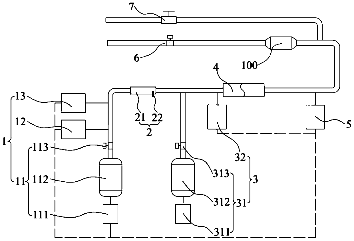
The invention, which relates to the technical field of engines, provides an emission generation test device comprising a raw material supply mechanism, a combustion mechanism, an adjusting mechanism and a detection mechanism. The raw material supply mechanism and the combustion mechanism can provide raw materials like air, sulfur-containing fuel oil having a preset sulfur content, nitrogen-containing fuel with a preset nitrogen content and enable the raw materials to be fixed and combusted to generate emissions, wherein the concentrations of sulfur oxide, nitrogen oxide and other pollutants ofthe emissions are fixed. The detection mechanism detects component concentrations, temperatures, humidity and the like of emissions and feeds back results to the raw material supply mechanism and theadjusting mechanism; the raw material supply mechanism adjusts ratios of all raw materials in real time to change the component concentrations of the emissions; and the adjusting mechanism adjusts the temperatures and humidity of the emissions to realize accurate control of the component concentrations, temperatures and humidity of the emissions. Therefore, the test use of the to-be-tested emission post-treatment equipment is facilitated and the time and labor are saved.

Description

technical field [0001] The invention relates to the technical field of engines, in particular to an emission generation test device. Background technique [0002] In order to meet the requirements of environmental protection, people usually use exhaust after-treatment equipment to treat the emissions such as sulfur oxides and nitrogen oxides in the engine exhaust. [0003] When developing post-discharge treatment equipment, R&D personnel need to use the emission generation device to test the post-discharge treatment equipment to accurately obtain the performance of the post-discharge treatment equipment for the treatment of emissions. At present, in the mid-sample test for exhaust after-treatment equipment, researchers usually directly use the engine to obtain emissions to test the exhaust after-treatment equipment. [0004] However, due to the influence of the engine load point, even if the other test conditions remain unchanged, the component concentrations of sulfur oxid...

Claims


Application Information

Patent Timeline
IPC IPC(8): G01M15/02F23C7/00F23N1/00F23D11/40
CPCF23C7/002F23D11/40F23N1/00G01M15/02
Inventor 田新娜桂勇夏倩
Owner CSSC POWER INST CO LTD
Learn More