
motor

A technology for motors and bearing sleeves, applied in the field of motors, can solve problems affecting the smoothness of motor operation and magnetic leakage of magnetic parts 92, etc., and achieve the effect of improving the convenience of assembly, improving the safety of use, and improving the stability of assembly

Active Publication Date: 2021-07-23
SUNONWEALTH ELECTRIC MACHINE IND
View PDF8 Cites 0 Cited by
  • Summary
  • Abstract
  • Description
  • Claims
  • Application Information

AI Technical Summary

Problems solved by technology

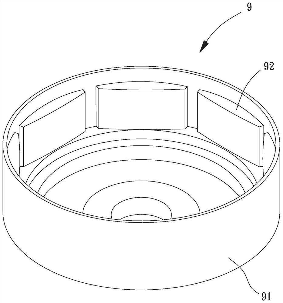
[0003] The above-mentioned existing motor rotor 9 can be matched with a stator to form a motor, but the plurality of magnetic parts 92 are directly combined with the base body 91, so if leakage occurs during operation of the motor, the leakage will easily pass through at least one of the aforementioned The magnetic parts 92 are conducted to the base body 91. In addition to fear of electric shock to the user, there are safety concerns, and magnetic flux leakage will occur in the multiple magnetic parts 92, which will affect the smoothness of the overall motor operation.

Method used


Image

  • motor
  • motor
  • motor

Examples


Embodiment Construction

[0060] In order to make the above-mentioned and other objects, features and advantages of the present invention more obvious and understandable, the preferred embodiments of the present invention are listed below, together with the accompanying drawings, and are described in detail as follows:

[0061] In the present invention, the directionality described below or its approximate terms, such as "front", "rear", "left", "right", "up (top)", "down (bottom)", "inside", "outside" , "side", etc., mainly refer to the directions of the drawings, and each direction or its approximate terms are only used to assist in explaining and understanding the various embodiments of the present invention, and are not intended to limit the present invention.

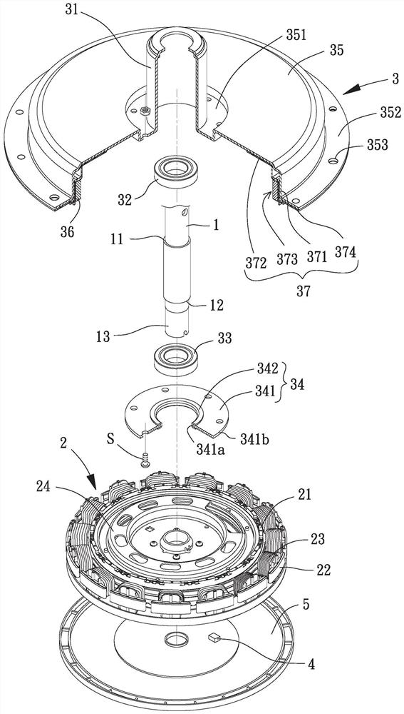
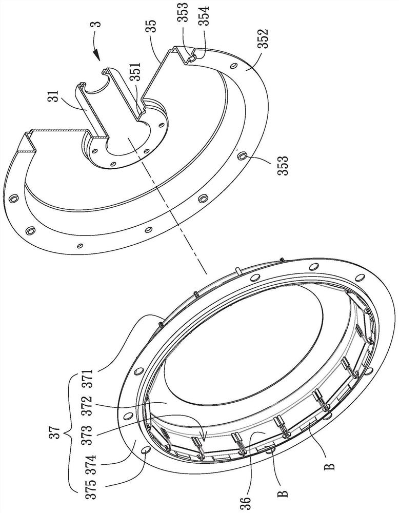
[0062] Please refer to figure 2 , which is the first embodiment of the motor of the present invention, comprising a mandrel 1, a stator group 2 and a rotor group 3, the stator group 2 is arranged on the outer periphery of the mandrel 1, an...


PUM


Abstract

The invention relates to a motor, which is used to solve the problems of the existing motors such as leakage of electricity to the outer surface of the rotor through magnetic parts, resulting in poor use safety and unsmooth operation. The motor of the present invention includes: a mandrel; a stator set arranged on the outer periphery of the mandrel; and a rotor set having a bearing sleeve and a first bearing and a second bearing accommodated in the bearing sleeve, the The first bearing and the second bearing are arranged on the core shaft, the rotor set has an extension plate connected to the outer circumference of the bearing sleeve, the rotor set has at least one magnetic part arranged inside the extension plate, the magnetic part and the The extension plates are separated by an insulating piece.

Description

technical field [0001] The invention relates to a motor, in particular to a motor capable of preventing electric leakage to the outer surface of a rotor through a magnetic part. Background technique [0002] Please refer to figure 1 , which is an existing motor rotor 9, the existing motor rotor 9 has a seat body 91 and a plurality of magnetic parts 92, and the plurality of magnetic parts 92 are respectively combined and fixed on the inner peripheral wall of the seat body 91, and spaced apart from each other. An embodiment similar to the conventional motor rotor 9 has been disclosed in Taiwan Patent Application Publication No. 200910738 "External Rotation Ceiling Fan Motor Rotor with Shock Absorbing and Noise Reducing Effects". [0003] The above-mentioned existing motor rotor 9 can be matched with a stator to form a motor, but the plurality of magnetic parts 92 are directly combined with the base body 91, so if leakage occurs during operation of the motor, the leakage will...

Claims


Application Information

Patent Timeline
Patent Type & Authority Patents(China)
IPC IPC(8): H02K1/27H02K5/16H02K3/34
CPCH02K1/2706H02K3/345H02K5/161
Inventor 洪银树邱柏伟杨坤达
Owner SUNONWEALTH ELECTRIC MACHINE IND
Learn More