Positioning and clamping mechanism for stock solution stirring barrel

A technology of clamping mechanism and mixing barrel, which is applied in the direction of mixer accessories, mixers, dissolving, etc., can solve the problems of loose locking and easy sliding, etc., and achieve the effect of firm clamping and positioning, not easy to slide, and good effect

Inactive Publication Date: 2020-02-04
佛山艾嘉化妆品有限公司
View PDF0 Cites 0 Cited by
  • Summary
  • Abstract
  • Description
  • Claims
  • Application Information

AI Technical Summary

Problems solved by technology

[0002] The barrel body of the existing raw material mixing barrel needs to be fixed before stirring, and the existing fixing mechanism is to place the raw material mixing barrel between two clamping frames, and fix it by two clamping frames, and the clamping frame When the left and right position of the holder moves, the connecting rod

Method used


Image

  • Positioning and clamping mechanism for stock solution stirring barrel
  • Positioning and clamping mechanism for stock solution stirring barrel

Examples


Example Embodiment

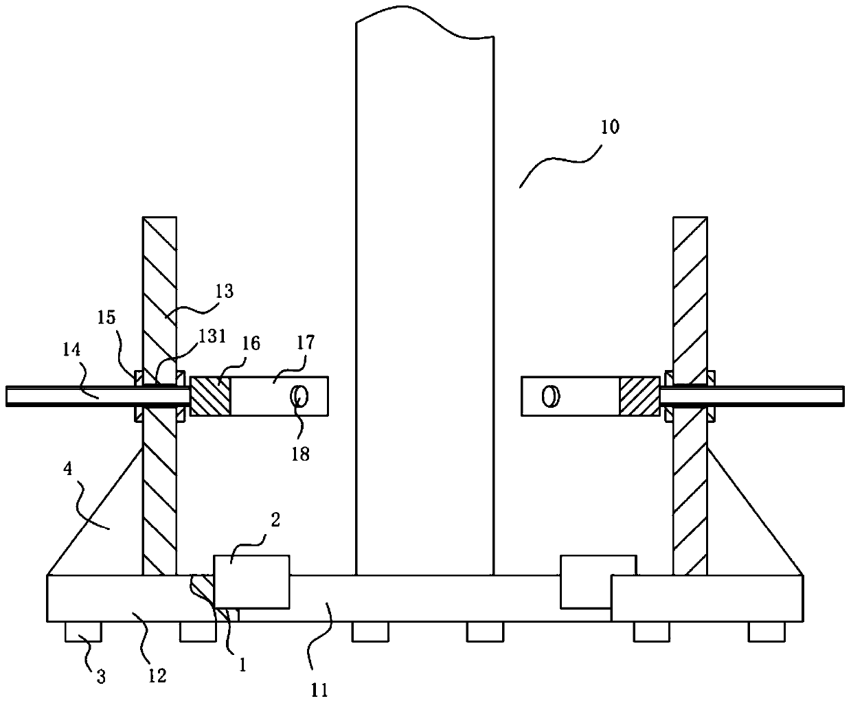
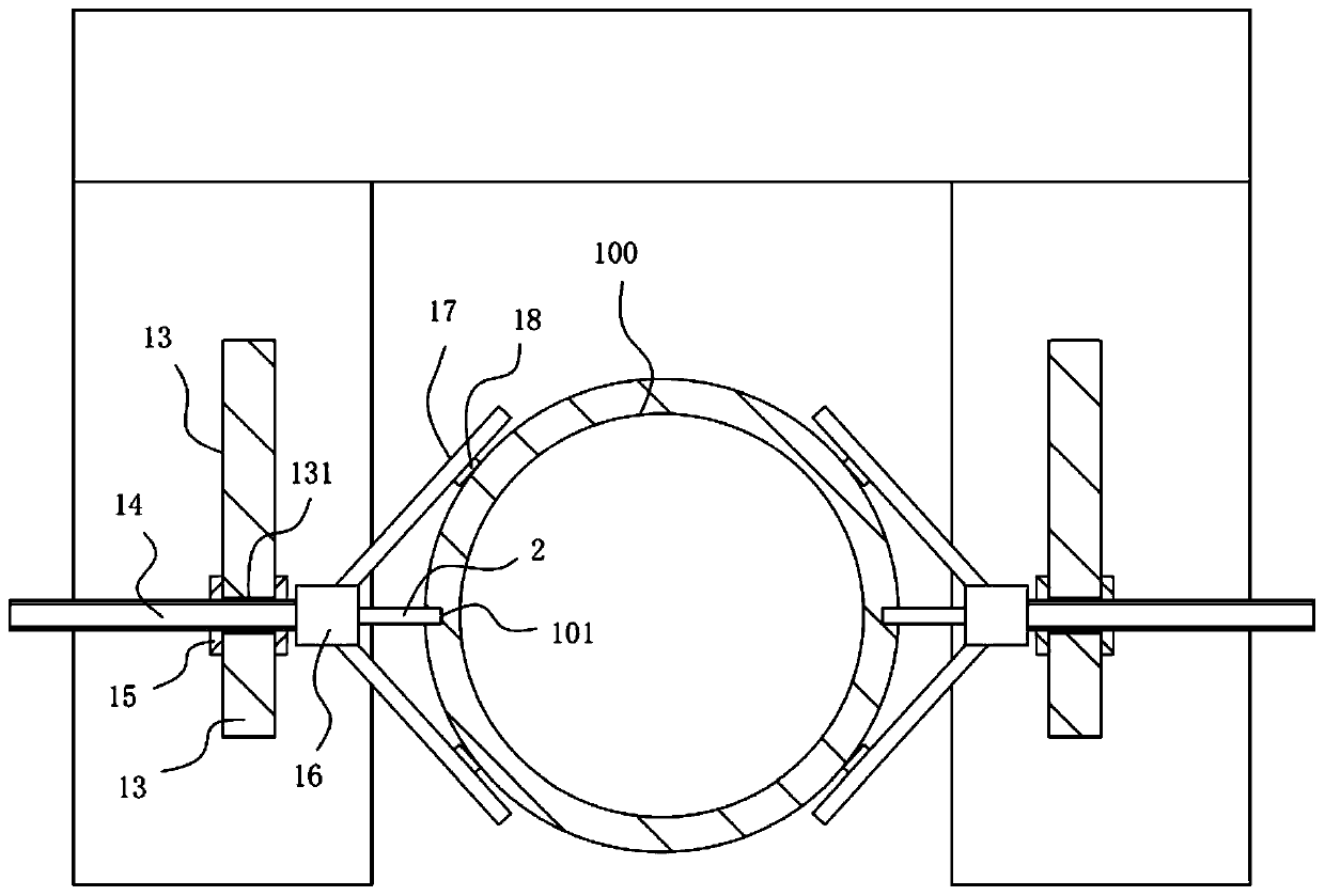
[0016] Example: see Figure 1 to Figure 2 As shown, a positioning and clamping mechanism for a raw liquid mixing barrel includes a bottom frame 10, the bottom frame 10 includes a rear connecting plate 11, and the left and right sides of the front wall surface of the rear connecting plate 11 are fixed with front extension plates 12, two The top surface of the front extension plate 12 is fixed with a vertical plate 13, and the middle of the two vertical plates 13 is formed with a socket 131, the adjusting screw 14 is inserted into the corresponding socket 131, and the adjusting screw 14 is screwed Two lock nuts 15, the vertical plate 13 is clamped between the two lock nuts 15;

[0017] The inner ends of the two adjusting screws 14 on the two vertical plates 13 protrude from the inner side wall of the vertical plate 13 and are fixed with a main connecting block 16. The front and rear side walls of the main connecting block 16 are fixed with oblique To the rod 17.

[0018] Furthermor...


PUM


Abstract

The invention discloses a positioning and clamping mechanism for a stock solution stirring barrel. The positioning and clamping mechanism comprises a bottom rack, the bottom rack comprises a rear connecting plate, front extending plates are fixed to the left side and the right side of the front wall surface of the rear connecting plate correspondingly, vertical plates are fixed to the top surfacesof the two front extending plates correspondingly, inserting holes are formed in the middles of the two vertical plates correspondingly, adjusting screw rods are inserted into the corresponding inserting holes in a sleeved mode, two locking nuts are connected to the adjusting screw rods in a threaded mode, and the vertical plates are clamped between the two locking nuts. The adjusting screw rodscan move left and right along the vertical plates, and then the two locking nuts are rotated to make the vertical plate clamped between the two locking nuts, so the positions of the adjusting screw rods are fixed, and the adjusting screw rods are not prone to sliding, are clamped firmly and have a good effect; and the two positioning blocks are inserted into positioning grooves formed in the lowerportion of the sidewall of a to-be-stirred barrel body to realize further positioning, prevent rotation of the to-be-stirred barrel body during stirring and achieve firm clamping and positioning.

Description

technical field [0001] The invention relates to the technical field of makeup equipment, and more specifically relates to a positioning and clamping mechanism for a stock solution mixing barrel. Background technique [0002] The barrel body of the existing raw material mixing barrel needs to be fixed before stirring, and the existing fixing mechanism is to place the raw material mixing barrel between two clamping frames, and fix it by two clamping frames, and the clamping frame When the left and right position of the holder moves, the connecting rod of the clamping frame moves left and right along the middle through hole of the support plate, and then the locking rod is screwed on the support plate, and the bottom end of the locking rod extends into the middle through hole to press it The connecting rod of the clamping frame is fixed, and it is easy to slide, and the locking is not firm. Contents of the invention [0003] The purpose of this invention is to address the de...

Claims


Application Information

Patent Timeline
IPC IPC(8): B01F15/00
CPCB01F35/42B01F2101/21
Inventor 苏志远
Owner 佛山艾嘉化妆品有限公司
Why Eureka
Try Eureka