Flame cutting machine for transformer shell production

A technology for flame cutting machines and transformer shells, which is applied in the direction of gas flame welding equipment, welding/cutting auxiliary equipment, auxiliary devices, etc., and can solve problems such as cumbersome clamping operations, large demand for transformer shell production, and waste of time

Inactive Publication Date: 2020-02-04
HUNAN CITY UNIV
View PDF8 Cites 0 Cited by
  • Summary
  • Abstract
  • Description
  • Claims
  • Application Information

AI Technical Summary

Problems solved by technology

[0002] The demand for the production of transformer shells is large, so efficiency is emphasized during processing. The traditional flame cutting machine is cumbersome to clamp the workpiece during processing, which wastes a lot of time. In view of this, we propose a flame cutting machine for the production of transformer shells. machine

Method used


Image

  • Flame cutting machine for transformer shell production
  • Flame cutting machine for transformer shell production
  • Flame cutting machine for transformer shell production

Examples


Embodiment Construction

[0024] The following will clearly and completely describe the technical solutions in the embodiments of the present invention with reference to the accompanying drawings in the embodiments of the present invention. Obviously, the described embodiments are only some, not all, embodiments of the present invention. Based on the embodiments of the present invention, all other embodiments obtained by persons of ordinary skill in the art without making creative efforts belong to the protection scope of the present invention.

[0025] In describing the present invention, it should be understood that the terms "center", "longitudinal", "transverse", "length", "width", "thickness", "upper", "lower", "front", " Orientation indicated by rear, left, right, vertical, horizontal, top, bottom, inside, outside, clockwise, counterclockwise, etc. The positional relationship is based on the orientation or positional relationship shown in the drawings, and is only for the convenience of describin...


PUM


Abstract

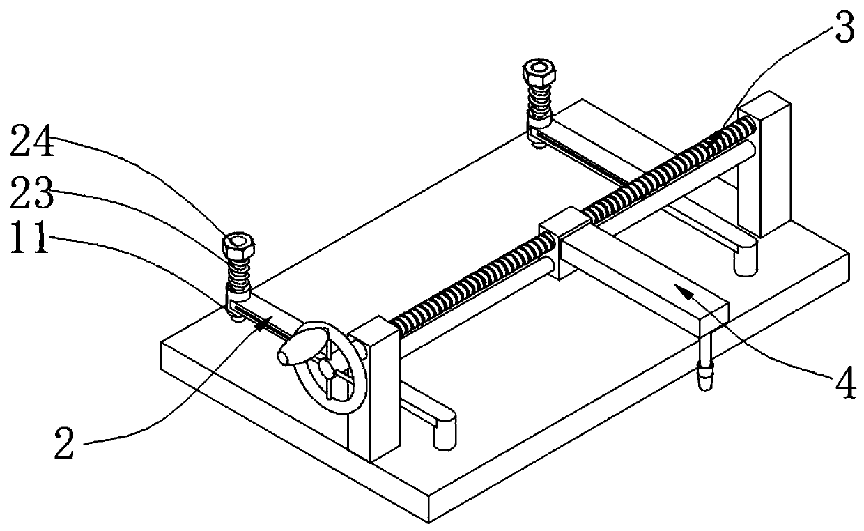
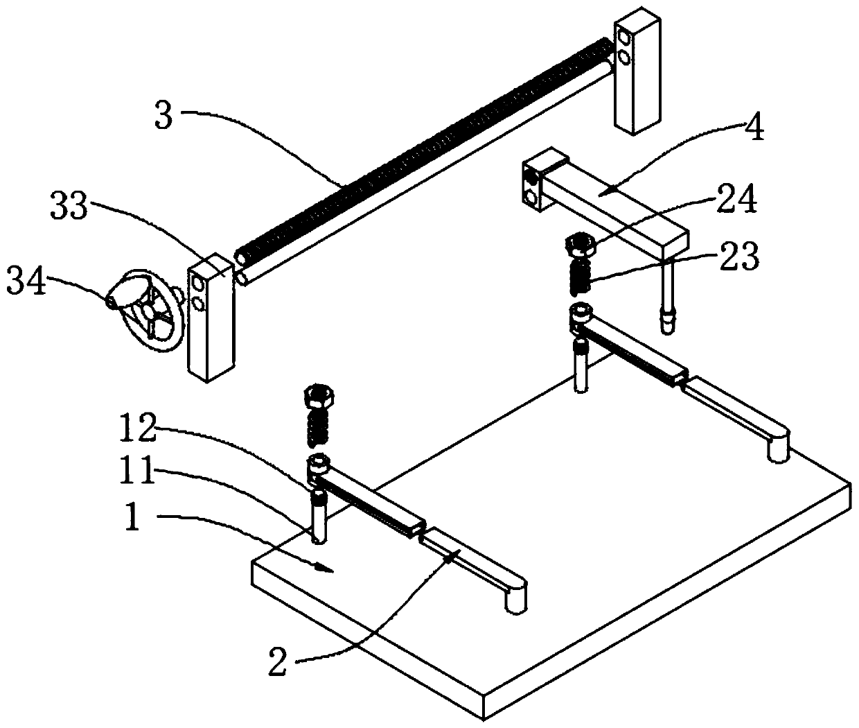
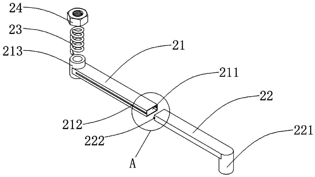
The invention relates to the technical field of transformer production, in particular to a flame cutting machine for transformer shell production. The flame cutting machine comprises a bottom plate, two fixed columns are arranged at the positions, close to one side, of the upper end of the bottom plate, and threads are arranged at the top ends of the fixed columns. The bottom plate is provided with fixed swing rods, the fixed swing rods include rotating rods, sliding holes are formed in the rotating rods, sliding grooves are formed in the two sides of the rotating rods in a penetrating mode, the sliding grooves extend into the sliding holes, rotating columns are arranged at one ends of the rotating rods, the rotating columns are arranged on the fixed columns in a sleeving mode, and the rotating rods are internally provided with sliding rods. The sliding rods and the rotating rods are slidably connected to achieve the convenient expansion and contraction of the fixed swing rods. Throughthe rotating connection between the rotating columns and the fixed columns, the swing of the fixed swing rods is realized. The rotating columns are pressed by springs to achieve the convenient lifting of the fixed swing rods and convenient pressing and fixing of workpieces, and the technical problems in the technical background of the invention are solved.

Description

technical field [0001] The invention relates to the technical field of transformer production, in particular to a flame cutting machine for transformer shell production. Background technique [0002] The demand for the production of transformer shells is large, so efficiency is emphasized during processing. The traditional flame cutting machine is cumbersome to clamp the workpiece during processing, which wastes a lot of time. In view of this, we propose a flame cutting machine for the production of transformer shells. machine. Contents of the invention [0003] The object of the present invention is to provide a flame cutting machine for transformer casing production to solve the problems raised in the above-mentioned background technology. [0004] To achieve the above object, the present invention provides the following technical solutions: [0005] A flame cutting machine for the production of transformer shells, comprising a base plate, two fixing columns are arrang...

Claims


Application Information

Patent Timeline
Patent Type & Authority Applications(China)
IPC IPC(8): B23K7/00B23K7/10B23K37/04
CPCB23K7/00B23K7/10B23K37/04
Inventor 范彬余志娟
Owner HUNAN CITY UNIV
Why Eureka
Try Eureka