
Device and method for lifting engine accessory gearboxes and inhibiting damage

An accessory casing and engine technology, applied in the directions of transportation and packaging, load hanging components, etc., can solve the problems of scrap parts, rework and repair of parts, disassembly of the engine casing of the damaged engine connection part, etc., to prevent bumps, reduce Bump rate, easy adjustment effect

Active Publication Date: 2020-02-04
PLA NO 5719 FACTORY
View PDF7 Cites 2 Cited by
  • Summary
  • Abstract
  • Description
  • Claims
  • Application Information

AI Technical Summary

Problems solved by technology

However, during the hoisting process using two steel ropes or a simple sling, because the center point of the engine accessory casing cannot be kept balanced, the conduit and the engine casing of the engine connection part are often damaged during disassembly and installation, resulting in Parts rework repair and some parts scrapped

Method used


Image

  • Device and method for lifting engine accessory gearboxes and inhibiting damage
  • Device and method for lifting engine accessory gearboxes and inhibiting damage

Examples


Embodiment 1

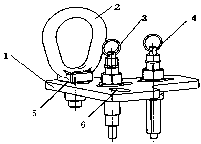
[0022] Such as figure 1 As shown, the embodiment of the present invention provides a device for suppressing bruises during hoisting of an engine accessory casing, which includes: a hanging plate 1, the hanging plate 1 is provided with a first through hole, a second through hole and a third through hole;

[0023] The suspension ring device, the suspension ring device includes suspension ring 2 and the suspension ring fixing part connected with the bottom of the suspension ring 2, the suspension ring fixing part penetrates and cooperates with the first through hole and is connected with the suspension plate 1,

[0024] The first connecting shaft 3, the first connecting shaft 3 fits through the second through hole and is connected with the suspension plate 1, the bottom of the first connecting shaft 3 can be detachably connected with the engine accessory casing;

[0025] The second connecting shaft 4, the second connecting shaft 4 fits through the third through hole and is connec...

Embodiment 2

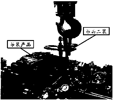
[0033] refer to figure 2 , this embodiment also provides a method for suppressing bruises during hoisting of an engine accessory casing, which includes: connecting the ring device, the first connecting shaft 3 and the second connecting shaft 4 to the hanging plate 1, and connecting the bottom of the first shaft And the bottom of the second shaft is threadedly connected with the threaded holes on the engine accessory casing respectively, and then the hoisting mechanism hooks the suspension ring 2 on the suspension ring device for lifting.

[0034] The invention has the following advantages: 1. It is convenient to adjust. The present invention uses two stress points for hoisting, which can conveniently adjust whether the main fuel pump is installed on the engine accessory casing, thereby ensuring the balance requirement of the engine accessory casing during the entire hoisting process

[0035] 2. During the installation and disassembly process of the engine accessory casing, t...


PUM


Abstract

The invention discloses a device and method for lifting engine accessory gearboxes and inhibiting damage and relates to the technical field of aviation engine lifting. The device comprises a lifting plate, a lifting ring device, a first connecting shaft and a second connecting shaft, wherein a first through hole, a second through hole and a third through hole are arranged in the lifting plate; thelifting ring device comprises a lifting ring and a lifting ring fixing component connected with the bottom of the lifting ring; the lifting ring fixing component penetrates through the first throughhole and is connected with the lifting plate; the first connecting shaft penetrates through the second through hole and is connected with the lifting plate, and the bottom of the first connecting shaft can be detachably connected with an engine accessory gearbox; and the second connecting shaft penetrates through the third through hole and is connected with the lifting plate, and the bottom of thesecond connecting shaft can be detachably connected with the engine accessory gearbox. The device and the method have the advantages that regulation is convenient, and the damage of the parts of theengine accessory gearbox and the scrapping of part of parts can be effectively prevented.

Description

technical field [0001] The invention relates to the technical field of aero-engine hoisting, in particular to a device and method for hoisting an engine accessory casing to suppress damage. Background technique [0002] After the engine enters the factory, during the overhaul or overhaul process, the engine accessory casing needs to be disassembled. During the field use, the engine accessory casing often suffers from excessive faults of metal components such as copper and aluminum due to design defects and other reasons. In order to solve this problem, the prior art generally adopts two steel ropes or adopts a simple spreader to carry out the lifting work of dismounting and installing. However, during the hoisting process using two steel ropes or a simple sling, because the center point of the engine accessory casing cannot be kept balanced, the conduit and the engine casing of the engine connection part are often damaged during disassembly and installation, resulting in Pa...

Claims


Application Information

Patent Timeline
IPC IPC(8): B66C1/62
CPCB66C1/107B66C1/62
Inventor 谌青军唐胜赵一鸣谭广义
Owner PLA NO 5719 FACTORY
Learn More