Cooling structure of motor

A cooling structure and motor technology, applied in the field of motors, can solve problems such as poor stability, waste of energy, and poor cooling and cooling effects, and achieve the effects of improving stability and safety, saving energy, and improving effects

Active Publication Date: 2020-02-04
山东宇恒智能动力科技有限公司
View PDF6 Cites 2 Cited by
  • Summary
  • Abstract
  • Description
  • Claims
  • Application Information

AI Technical Summary

Problems solved by technology

[0003] At present, there are still some deficiencies in the existing motor cooling device, for example; the existing motor cooling device only uses water cooling, the cooling effect is not very good, and it needs to use additional driving equipment for water cooling cycle, which is wasteful Energy, not only that, when the existing motor is connected to a large object, the stability is not very good

Method used


Image

  • Cooling structure of motor
  • Cooling structure of motor
  • Cooling structure of motor

Examples


Embodiment Construction

[0025] In order to make the technical means, creative features, goals and effects achieved by the present invention easy to understand, the present invention will be further described below in conjunction with specific embodiments.

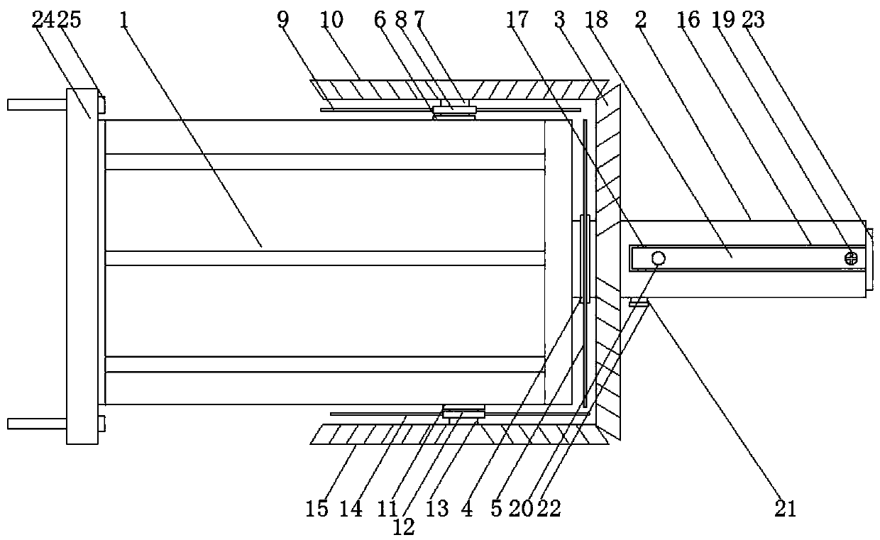
[0026] see Figure 1-4 , the present invention provides a technical solution: a motor cooling structure, including a motor body 1, the outer side of the motor body 1 is provided with a main cooling mechanism, a connecting mechanism and an auxiliary cooling mechanism;

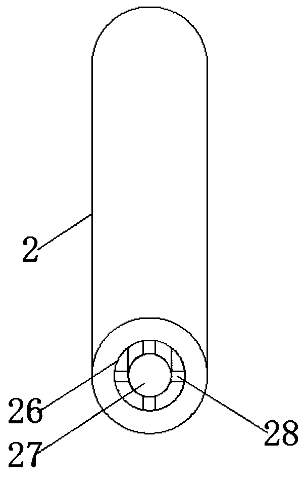
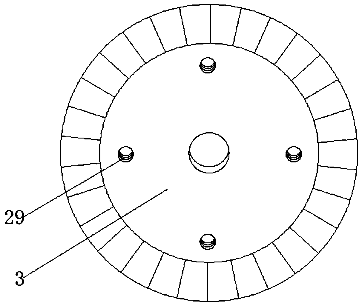
[0027] The main cooling structure includes a motor shaft 2, a first fixed ring 4, a first fan blade 5, a second fixed ring 8, a second fan blade 9, a third fixed ring 12, a third fan blade 14, a One bearing 6, the second bearing 11, the first rotating rod 7, the second rotating rod 13, the first bevel gear 3, the second bevel gear 10 and the third bevel gear 15; the right side of the motor body 1 is connected with a motor Shaft 2, the right side of the motor shaft 2 passes through ...


PUM


Abstract

The invention discloses a cooling structure of a motor, which comprises a motor body, wherein the outer side of the motor body is provided with a main cooling mechanism, a connecting mechanism and anauxiliary cooling mechanism; the main cooling structure comprises a motor shaft, a first fixing ring, a first draft fan blade, a second fixing ring, a second draft fan blade, a third fixing ring, a third draft fan blade, a first bearing, a second bearing, a first rotating rod, a second rotating rod, a first bevel gear, a second bevel gear and a third bevel gear. According to the invention, the first bevel gear on the motor shaft and the second bevel gear and the third bevel gear on the motor body are arranged, and the three bevel gears can be driven to rotate when the motor shaft rotates, so that the first draft fan blade, the second draft fan blade and the third draft fan blade rotate are enabled to rotate, air draft is conducted from the upper side, the lower side and the right side at the same time to perform cooling on the motor. In addition, extra driving equipment is not needed, and energy is saved.

Description

technical field [0001] The invention relates to the technical field of electric motors, in particular to a cooling structure for electric motors. Background technique [0002] Patent No. CN201620771248.2 discloses a motor cooling device related to the technical field of motor cooling equipment, including a cooling box, the cooling box is equipped with an air inlet, an air outlet, and an axial fan, and the air inlet is located in the cooling box Above the front of the body, the air outlet is located above the rear of the cooling box, and the axial flow fan is located at the rear of the cooling box. There is a bent partition plate in the cooling box. The bent partition plate is composed of a horizontal plate and a longitudinal plate. The horizontal plate is provided with evenly distributed air holes. The cooling box is divided into a water-cooling area and a drying area. The water-cooling area is provided with a water-cooling device, and the drying area is provided with at le...

Claims


Application Information

Patent Timeline
Patent Type & Authority Applications(China)
IPC IPC(8): H02K9/06H02K9/19H02K5/24
CPCH02K5/24H02K9/06H02K9/19
Inventor 张红卫
Owner 山东宇恒智能动力科技有限公司
Why Eureka
Try Eureka