Novel fire hydrant

A fire hydrant, a new type of technology, used in fire rescue and other directions to reduce internal wear, prevent water, and increase service life

Inactive Publication Date: 2020-02-07
罗红
View PDF0 Cites 0 Cited by
  • Summary
  • Abstract
  • Description
  • Claims
  • Application Information

AI Technical Summary

Problems solved by technology

[0004] Based on the above problems, the present invention provides a new type of fire hydrant, in order to solve the problem of quickly connecting the water outlet before eliminating the fire source and quickly blocking the water outlet after eliminating the fire source, reducing the internal wear of the fire hydrant, increasing the service life, etc. question

Method used


Image

  • Novel fire hydrant
  • Novel fire hydrant

Examples


Embodiment 1

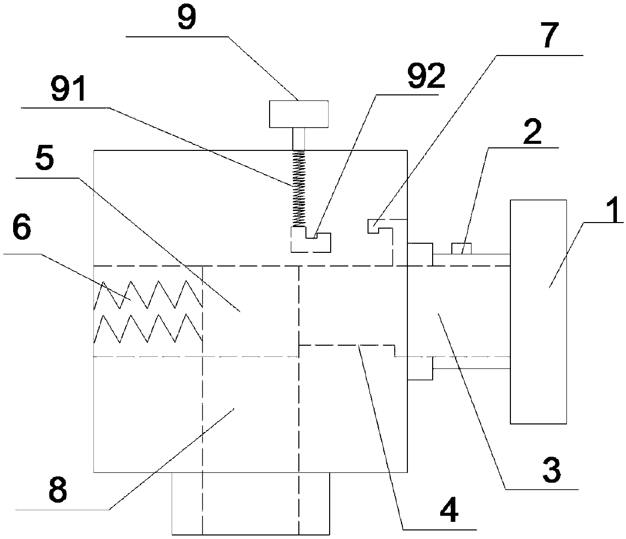
[0022] see Figure 1~2 , a new type of fire hydrant, comprising the connecting seat 1 and an internal moving water pipe 3, the connecting seat 1 is connected to the internal moving water pipe 3, the inner water pipe nozzle 4 is connected to a fixed water pipe 8; the internal moving water pipe 3 includes an internal Water pipe nozzle 4, magnetic block 5, spring tube 6, convex groove 7, described magnetic block 5 is cylindrical, and described magnetic block 5 is positioned at the junction of inner moving water pipe 3 and fixed water pipe 8, and described magnetic block 5 follows The inner moving water pipe 3 moves, and the outer diameter of the magnetic block 5 is equal to the outer diameter of the spring tube 6, and a fixed water pipe 8 is arranged below the magnetic block 5, and the outer diameter of the fixed water pipe 8 is the same as that of the magnetic block 5. The top of the internal moving water pipe 3 is provided with a convex groove 7, and the convex groove 7 moves w...

Embodiment 2

[0025] see Figure 1~2 , a new type of fire hydrant, comprising the connecting seat 1 and an internal moving water pipe 3, the connecting seat 1 is connected to the internal moving water pipe 3, the inner water pipe nozzle 4 is connected to a fixed water pipe 8; the internal moving water pipe 3 includes an internal Water pipe nozzle 4, magnetic block 5, spring tube 6, convex groove 7, described magnetic block 5 is cylindrical, and described magnetic block 5 is positioned at the junction of inner moving water pipe 3 and fixed water pipe 8, and described magnetic block 5 follows The inner moving water pipe 3 moves, and the outer diameter of the magnetic block 5 is equal to the outer diameter of the spring tube 6, and a fixed water pipe 8 is arranged below the magnetic block 5, and the outer diameter of the fixed water pipe 8 is the same as that of the magnetic block 5. The top of the internal moving water pipe 3 is provided with a convex groove 7, and the convex groove 7 moves w...

Embodiment 3

[0028] see Figure 1~2 , a new type of fire hydrant, comprising the connecting seat 1 and an internal moving water pipe 3, the connecting seat 1 is connected to the internal moving water pipe 3, the inner water pipe nozzle 4 is connected to a fixed water pipe 8; the internal moving water pipe 3 includes an internal Water pipe nozzle 4, magnetic block 5, spring tube 6, convex groove 7, described magnetic block 5 is cylindrical, and described magnetic block 5 is positioned at the junction of inner moving water pipe 3 and fixed water pipe 8, and described magnetic block 5 follows The inner moving water pipe 3 moves, and the outer diameter of the magnetic block 5 is equal to the outer diameter of the spring tube 6, and a fixed water pipe 8 is arranged below the magnetic block 5, and the outer diameter of the fixed water pipe 8 is the same as that of the magnetic block 5. The top of the internal moving water pipe 3 is provided with a convex groove 7, and the convex groove 7 moves w...


PUM


Abstract

The invention relates to fire-fighting equipment, and discloses a novel fire hydrant. A fire hose is arranged outside a hydrant body, the fire hose is connected with an internal water pipe, and a firehose connecting base and the hydrant body are provided with opening iron columns. A button is arranged above the hydrant body, a spring is arranged below the button, a groove is arranged below the spring, the groove is tightly connected with the groove above the water pipe, and thus an internal water pipe lower opening is connected with a fixed water pipe. The novel fire hydrant can realize the purposes of quick blocking and connecting a water source, and achieves the effects that a water outlet can be rapidly connected before an ignition source is extinguished, water can be rapidly blocked after the ignition source is extinguished, internal abrasion of the hydrant is reduced, and the service life is prolonged.

Description

technical field [0001] The invention relates to a fire-fighting facility, in particular to a novel fire hydrant. Background technique [0002] Fire hydrants, officially called fire hydrants, are mainly used to control combustibles, isolate combustion aids, and eliminate ignition sources. The indoor fire hydrant is an important part of the fire water system. It is installed in the indoor fire box. Its fire extinguishing method is to connect the artificial water belt to the hydrant mouth to extinguish the fire. Usually, the indoor fire hydrant is connected with the screw and the handwheel, and it rotates under the drive of the handwheel. Screw to activate the disc to use. [0003] When using this kind of fire hydrant, due to the long screw rod, the speed of starting the valve disc is slow, and it takes more time and strength to start the valve disc. The valve disc is closed, so the connection between the screw and the valve disc is easy to be damaged, and it cannot be used f...

Claims


Application Information

Patent Timeline
Patent Type & Authority Applications(China)
IPC IPC(8): A62C35/20
CPCA62C35/20
Inventor 罗红
Owner 罗红
Why Eureka
Try Eureka