Boiler slag cooler and mounting method thereof

A slag cooler and boiler technology, applied in the direction of reducing greenhouse gases, climate sustainability, lighting and heating equipment, etc., can solve the problems of internal spiral blade wear, internal pipe wear, and reduce the output of the slag cooler, so as to reduce wear and tear. and internal stress, reducing internal wear and preventing water leakage

Inactive Publication Date: 2022-08-05
HUAINAN MINING IND GRP
View PDF1 Cites 0 Cited by
  • Summary
  • Abstract
  • Description
  • Claims
  • Application Information

AI Technical Summary

Problems solved by technology

[0003] During the use of existing slag coolers, the internal pipes are often severely worn, and the overall thickness is thinned. The internal spiral blades are severely worn, which greatly reduces the cooling capacity. The output of the slag machine is low, and the work efficiency is low, which affects the safe and stable operation of the unit
[0004] Chinese patent CN202927835U discloses a pipe row type drum slag cooling machine. In this patent, the slag conveying pipe is arranged in the middle, and an outer cylinder is arranged outside the slag conveying pipe. The outer cylinder and the slag conveying pipe form a closed water cavity, and a return pipe is set outside the water chamber to connect the return water pipe to the water outlet device. The slag conveying pipe is built with multiple spiral pieces, which solves the problem of insufficient slag discharge, easy coking, and slag conveying The pipe is easy to block and other disadvantages, but the inlet and outlet spiral pieces in this application are a structure, there is no difference from the beginning to the end, and the internal temperature of the slag cooling machine has different differences at different positions, and the effect of reducing loss of the same spiral piece is not as good as many Group and changing helical slices are good

Method used


Image

  • Boiler slag cooler and mounting method thereof
  • Boiler slag cooler and mounting method thereof
  • Boiler slag cooler and mounting method thereof

Examples


Embodiment Construction

[0044] In order to make the purposes, technical solutions and advantages of the embodiments of the present invention clearer, the technical solutions in the embodiments of the present invention will be clearly and completely described below in conjunction with the embodiments of the present invention. Obviously, the described embodiments are part of the present invention. examples, but not all examples. Based on the embodiments of the present invention, all other embodiments obtained by those of ordinary skill in the art without creative efforts shall fall within the protection scope of the present invention.

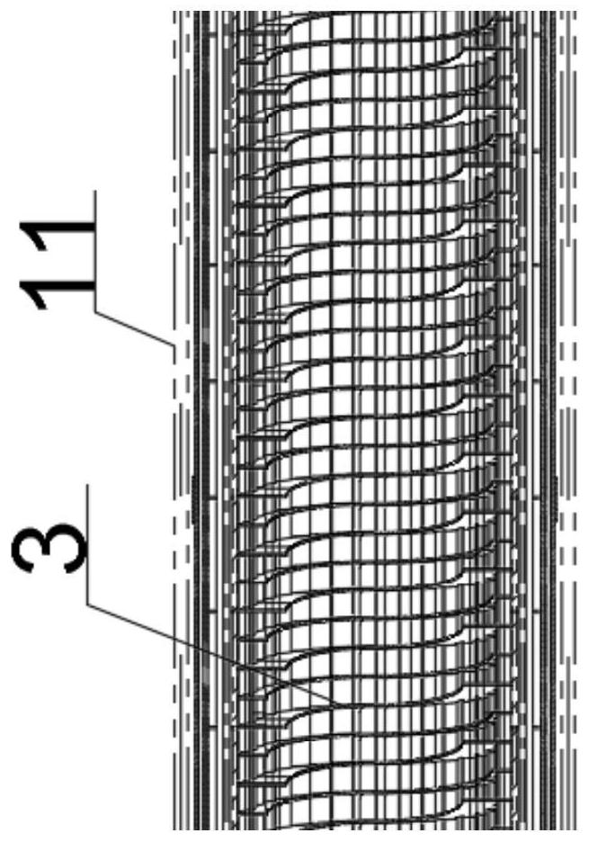
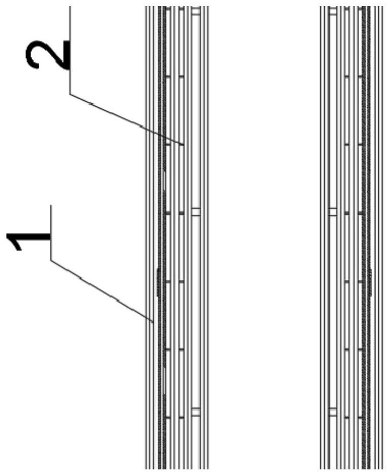
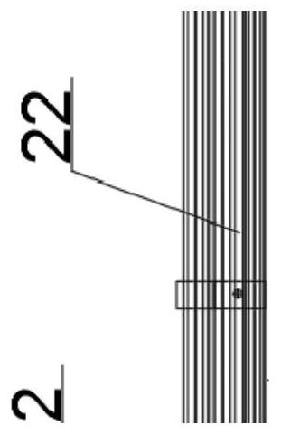
[0045] see figure 1 , This embodiment discloses a boiler slag cooler, including a cylinder body 1 , a tube row assembly 2 , a screw assembly 3 , and a cylinder mouth assembly 4 .

[0046] Also see Figure 1-2 , the cylinder body 1 has a "rectangular" structure as a whole. The left side of the cylinder body 1 is the inlet end, and the right side of the cylinder body 1 ...


PUM


Abstract

The invention discloses a boiler slag cooler and an installation method thereof.The left side of a barrel is an inlet end, the right side of the barrel is an outlet end, a tube bundle assembly is provided with a plurality of sets of inner cavities distributed in the barrel at equal intervals, the rightmost sides of all sets of finned tubes are jointly communicated with elbows, and the elbows are arranged in the inner cavities. The upper end of the elbow penetrates through an inner cavity of the barrel body and extends to the outer side to be communicated with the water collecting tank, a plurality of external water pipes are fixedly connected to the outer side of the barrel body, the spiral assembly is provided with a plurality of sets of inner cavities distributed in the barrel body at equal intervals, and the spiral assembly comprises a plurality of sets of different blades; according to the finned tube, the problem of a heating surface is effectively solved by increasing the diameter of the pipeline, increasing the number of the tube rows and changing the structure of the finned tube, meanwhile, the spiral pieces are replaced according to the actual condition of the barrel, and internal abrasion is further reduced; and the service life of the device is greatly prolonged.

Description

technical field [0001] The invention relates to a slag cooler, in particular to a boiler slag cooler and an installation method thereof. Background technique [0002] The slag cooler, also known as the slag cooler, is mainly composed of a cylinder, a slag inlet box, a slag discharge box, a power transmission device, a chassis and an electrical control system. A slag guide sheet is welded on the wall and the partition frame. [0003] Existing slag coolers often suffer from serious wear and tear on the internal pipes during use, and the overall thinning phenomenon occurs. [0004] Chinese patent CN202927835U discloses a tube row type drum slag cooler. In this patent, a slag conveying pipe is arranged in the middle, and an outer cylinder is arranged outside the slag conveying pipe, so that the outer cylinder and the slag conveying pipe form a closed water cavity, and the slag conveying pipe forms a closed water cavity. A return pipe is set outside the cavity to connect the re...

Claims


Application Information

Patent Timeline
Patent Type & Authority Applications(China)
IPC IPC(8): F23J1/06
CPCF23J1/06Y02E20/30
Inventor 马伯洲朱宗辉孙善武张大伟代雷
Owner HUAINAN MINING IND GRP
Why Eureka
Try Eureka