
Method and Installation for Pyrolisis of Tires

a technology of pyrolysis and tires, which is applied in the direction of gaseous fuels, mechanical conveying coke ovens, energy inputs, etc., can solve the problems of reducing the quality increasing energy losses, and reducing the yield of the obtained carbon product, so as to reduce the harmful impact of cracking on the quantity, reduce the temperature of the pyroliser, and reduce the effect of energy expenses

Inactive Publication Date: 2008-08-28
KOLEV DIMITAR NIKOLAEV +2
View PDF7 Cites 4 Cited by
  • Summary
  • Abstract
  • Description
  • Claims
  • Application Information

AI Technical Summary

Benefits of technology

[0010]The advantages of the tire pyrolysis method and installation are that the tires heating is performed directly by gases, which leads to reducing energy expenses compared to heating through a wall. Adding steam to the gas mixture and decreasing the temperature in the pyroliser reduce manifold the harmful impact of cracking on the quantity and quality of the products obtained from the pyrolysis, and the steam is recovered within this installation. The installation is especially efficient for pyrolysis of whole tires, as facilities hat do not allow crushing of the tires are provided for the trolleys that are used for supplying the tires into the pyroliser. When the tires soften as a result of the heating, their heating surface does not decrease.

Problems solved by technology

The known method and installation use indirect heating of tires which is effected through the pyrolizer's wall, and for that reason the exhaust gases are released with high temperature, which is the reason of an increase of energy losses.
Besides, the heating of the pyroliser's wall to a high temperature causes cracking of the hydrocarbons obtained from the pyrolysis, which leads to the decrease of their yield and the lowering of the quality of the obtained carbon product.

Method used


Image

  • Method and Installation for Pyrolisis of Tires
  • Method and Installation for Pyrolisis of Tires
  • Method and Installation for Pyrolisis of Tires

Examples


Embodiment Construction

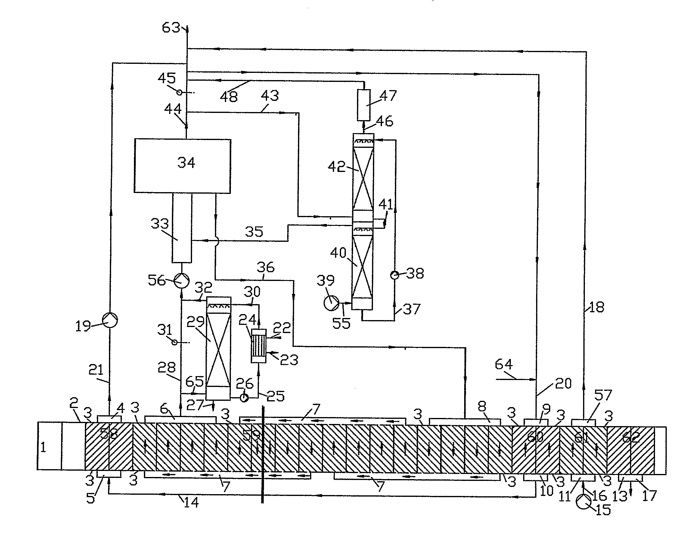
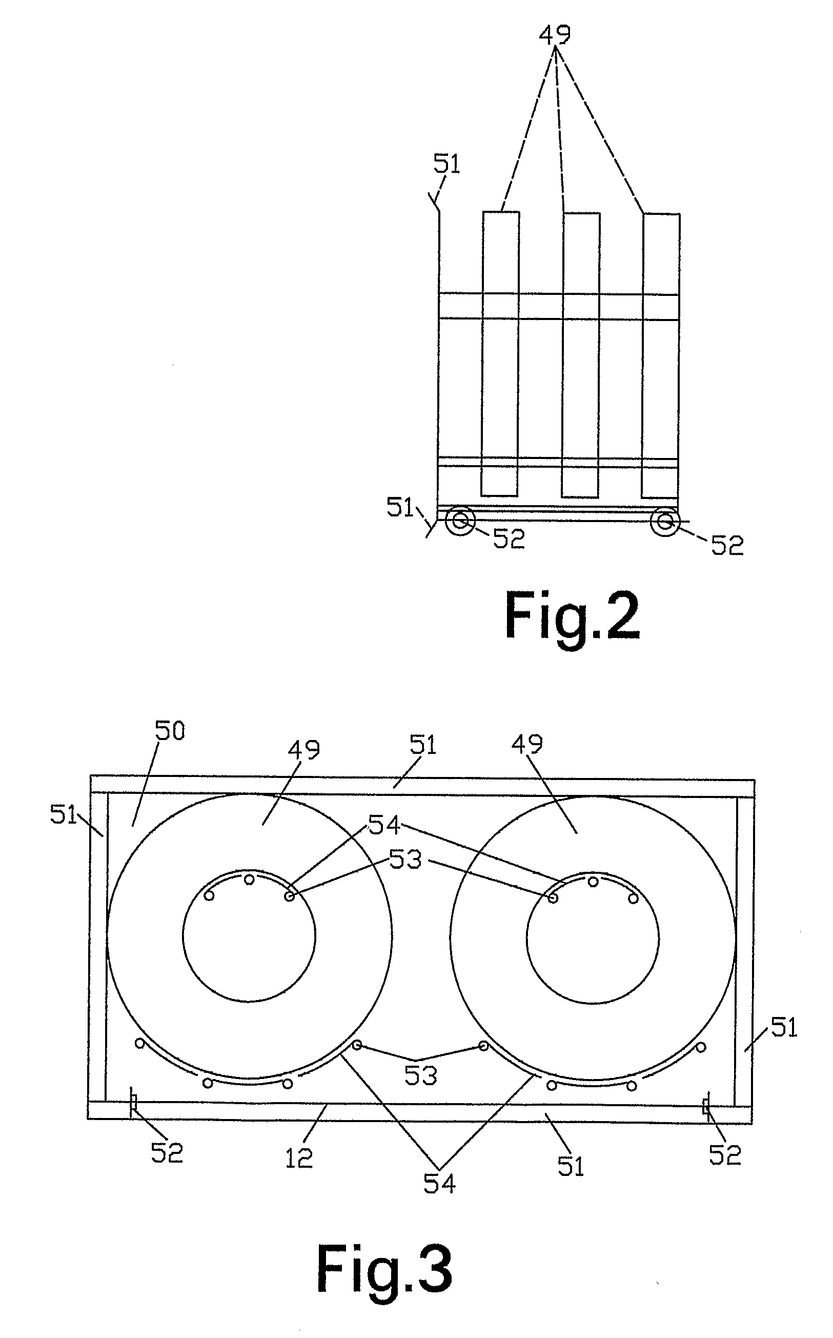
[0015]An example of the tire pyrolysis installation according to the invention, as shown on FIG. 1 includes a pyroliser 2, which represents a thermally insulated horizontal furnace channel. The trolleys 1 run on rails in it. The installation includes also a combustion chamber with a burner 33, a boiler 34, a contact economizer 42, an air humidifier 40, a direct cooler 29, a heat exchanger 24, fans 19, 39 and 56, and pumps 26 and 38. The trolleys 1 are made of profiles forming a frame, as it is shown on FIG. 2 and FIG. 3. A floor 12, made of compact metal sheets, and a vertical partition 50, located at the rear part of the trolley 1, are connected with this frame. This partition is shaped to follow the pyroliser 2 cross-section, and is sealed to the pyroliser walls by plates 51, tilted opposite to the trolley 1 movement direction. The plates 51 are connected by “hinges” with the trolley 1 and are tightened by tie-bars. Each trolley 1 has wheels 52. The trolleys are loaded with tires ...


PUM

PropertyMeasurementUnit
temperatureaaaaaaaaaa

Abstract

The present invention relates to a method and apparatus for waste tyres pyrolysis wherein whole tyres are directly heated with flue gases from the combustion of pyrolysis gases, in a tunnel type furnace. The process produces thermal energy, carbon black and mineral oil; the cooled flue gases are cleaned from sulfur oxides before released into the atmosphere.

Description

TECHNICAL FIELD [0001]The present invention relates to a method for waste tires pyrolysis and installation for its implementation and can be applied in the reprocessing of tires for the production of thermal energy, carbon black and mineral oil. The obtained carbon black may be used in the production of rubber articles, and the mineral oil—as fuel or softener in the production of such articles.BACKGROUND ART [0002]Document GB 2 303 859 makes known a method for pyrolysis of tires, processed in one piece or cut in big pieces, where the tires are heated indirectly to a temperature from 200 to 1000° C., preferably from 300 to 800° C., in a pyroliser, which is a horizontal channel, the tires being fed into it loaded in mobile trolleys. When heated, the tires pyrolize and pyrolysis gas, mineral oils' vapors exported with the pyrolysis gas, and solid carbon are obtained. The process takes place in three stages: heating of the tires, the process of pyrolysis itself, and cooling the obtained...

Claims


Application Information

Patent Timeline
Patent Type & Authority Applications(United States)
IPC IPC(8): C10B53/07C10B49/02C10G1/10C09C1/48
CPCC09C1/482C10B49/02C10G1/10C10G2300/1003C10B53/07Y02P20/129Y02P20/143
Inventor KOLEV, DIMITAR NIKOLAEVLJUTZKANOVA, RADKA BORISOVAABADJIEV, STEFAN TODOROV
Owner KOLEV DIMITAR NIKOLAEV
Learn More