Water-fire tube gas-steam boiler with built-in condenser

A technology of gas steam and condenser, which is applied in the direction of air heater, fluid heater, lighting and heating equipment, etc., which can solve the problems of large structure area, safety hazard and high steel consumption, and achieve small space occupation and area, safety Guaranteed performance and large heating surface

Inactive Publication Date: 2017-03-15
HARBIN INST OF TECH
View PDF6 Cites 4 Cited by
  • Summary
  • Abstract
  • Description
  • Claims
  • Application Information

AI Technical Summary

Problems solved by technology

[0009] The purpose of the present invention is to provide a water-fire tube gas-fired steam boiler with a built-in condenser, so as to solve the problems of the existing pyrotechnic tube steam boilers in the process of use, such as large structural footprint, potential safety hazards during operation, and higher steel consumption

Method used


Image

  • Water-fire tube gas-steam boiler with built-in condenser
  • Water-fire tube gas-steam boiler with built-in condenser
  • Water-fire tube gas-steam boiler with built-in condenser

Examples


specific Embodiment approach 1

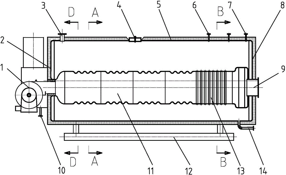
[0026] Specific implementation mode one: combine figure 1 , figure 2 , image 3 , Figure 4 and Figure 5 Describe this embodiment, this embodiment includes burner 1, steam pipe seat 3, shell 5, furnace 11, smoke pipe assembly 20, backfire chamber 26, condensing chamber 18 and smoke box 15, described furnace 11, smoke The pipe assembly 20, the backfire chamber 26 and the condensation chamber 18 are all arranged in the casing 5, the burner 1 is arranged outside the casing 5 and communicates with the inlet of the furnace 11, and the outlet of the furnace 11 is connected to the backfire The inlet of the chamber 26 is connected, the outlet of the reburning chamber 26 is connected with the inlet of the smoke pipe assembly 20, the outlet of the smoke pipe assembly 20 is connected with the inlet of the condensation chamber 18, and the smoke box 15 is arranged on the casing 5 and it communicates with the outlet of the condensation chamber 18, the smoke box 15 is processed with a ...

specific Embodiment approach 2

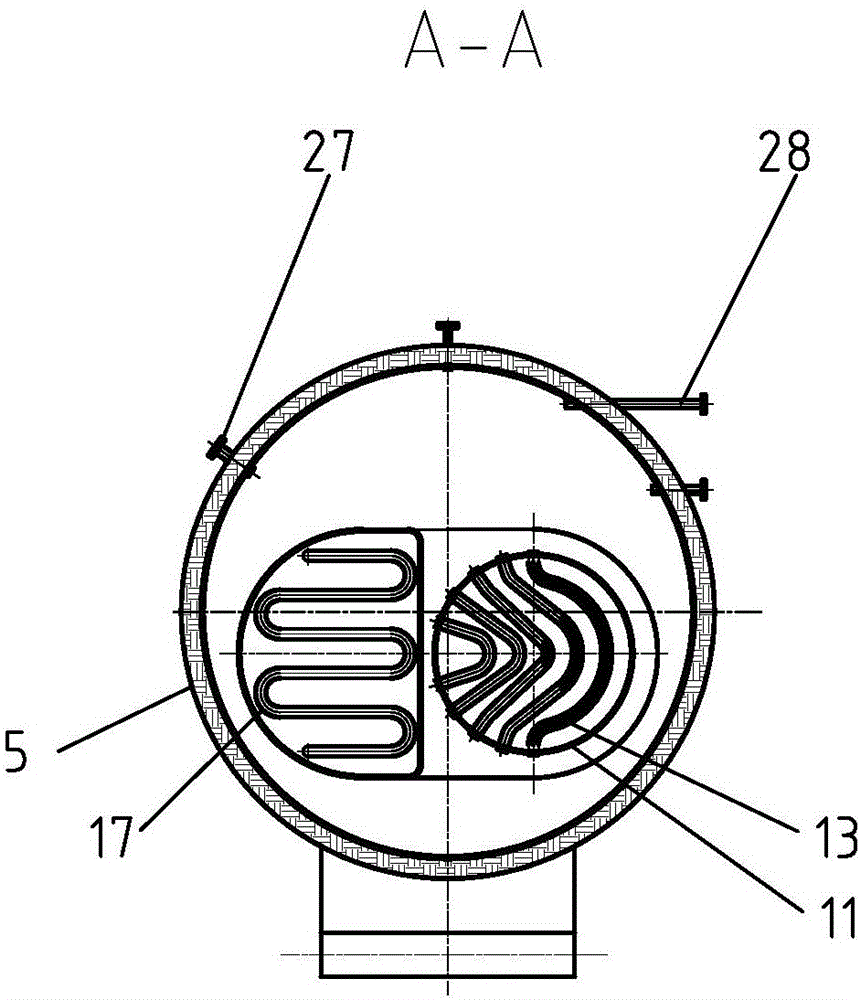
[0030] Specific implementation mode two: combination figure 2 and image 3 Describe this embodiment, the shape of the furnace 11 in the present embodiment is cylindrical and its outer wall is corrugated, multiple groups of convection tube bundles 13 are arranged near the outlet end of the furnace 11, and each group of convection tube bundles 13 includes a plurality of arc-shaped tube bundles, Both ends of each arc-shaped tube bundle are fixedly connected to the inner wall of the furnace 11, and two adjacent groups of convective tube bundles 13 are arranged in opposite directions.

[0031] In this embodiment, the shape of the furnace 11 is cylindrical and its outer wall is corrugated, that is, the furnace 11 has a corrugated cylindrical structure. Each group of convection tube bundles 13 is a plurality of arc-shaped tube bundles with different lengths. The multiple arc-shaped tube bundles are arranged in ascending order of length, and each arc-shaped tube bundle is bent. The ...

specific Embodiment approach 3

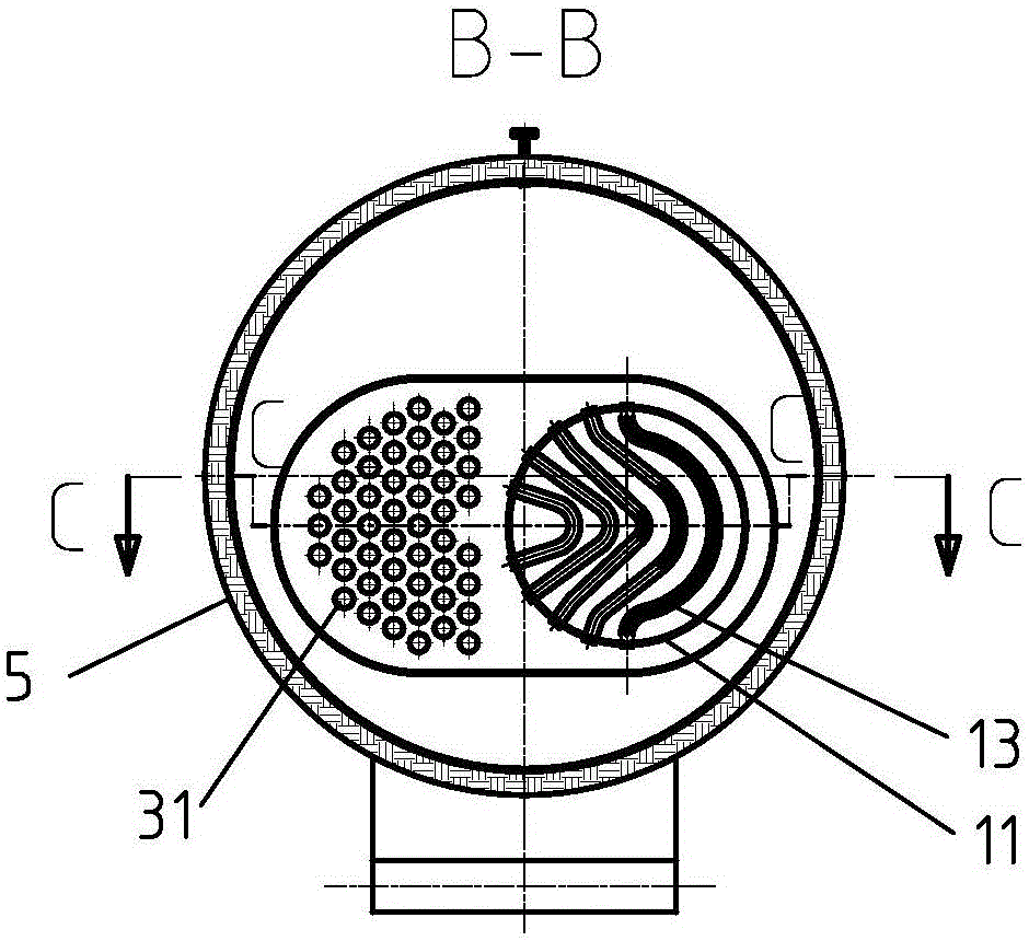
[0033] Specific implementation mode three: combination image 3 and Figure 4 Describe this embodiment, in this embodiment, the smoke pipe assembly 20 includes a plurality of single pipes 31, which are arranged side by side between the multiple single pipes 31, and one end of each single pipe 31 communicates with the front tube plate 22 for the combustion chamber. The other end of the single pipe 31 communicates with the condensation chamber 18 .

[0034] The arrangement of the smoke pipe assembly 20 in this embodiment is to provide a flow channel for the smoke. The single pipe 31 is a threaded pipe, a light pipe or a built-in spoiler. The single pipe 31 communicates with the condensation chamber 18 through the rear plate pipe 19 for the smoke pipe. Other unmentioned structures and connections are the same as those in the first or second embodiment.


PUM


Abstract

The invention provides a water-fire tube gas-steam boiler with a built-in condenser, and relates to a gas-steam boiler. An existing smoke-fire tube steam boiler has the problems that the structure occupies large floor area, potential safety hazards exist in the operation process, and steel consumption is high in the using process. The water-fire tube gas-steam boiler comprises a combustor, a steam tube base, a shell, a boiler furnace, a smoke tube assembly, a backdraft chamber, a condensation chamber and a smoke box; the boiler furnace, the smoke tube assembly, the backdraft chamber and the condensation chamber are all arranged in the shell, the combustor is arranged outside the shell and communicates with an inlet of the boiler furnace, an outlet of the boiler furnace communicates with an inlet of the backdraft chamber, an outlet of the backdraft chamber communicates with an inlet of the smoke tube assembly, an outlet of the smoke tube assembly communicates with an inlet of the condensation chamber, the smoke box is arranged outside the shell and communicates with an outlet of the condensation chamber, a smoke outlet is formed in the smoke box, multiple convection banks are arranged in the boiler furnace, condensation tube bundles are arranged in the condensation chamber, and the shell communicates with the steam pipe tube base. The water-fire tube gas-steam boiler is used for generating steam.

Description

technical field [0001] The invention specifically relates to a water-fire tube gas-fired steam boiler with a built-in condenser. Background technique [0002] Gas-fired steam boiler is a thermal energy conversion device that uses natural gas, liquefied petroleum gas, city gas, coke oven gas and other combustible gases as fuel, uses the heat released by the combustion of fuel in the furnace, heats the feed water entering the boiler, and vaporizes the water into steam. The water vapor output by the boiler is a form of secondary energy, which is widely used in various occasions that require steam in industry and life. [0003] There are many types of gas-fired steam boilers. Most of the large-scale steam boilers above 20t / h are water-tube boilers, such as D-type, O-type, box-type, etc. The furnace type of small and medium-sized gas-fired boilers below 20t / h is mainly internal combustion fire-tube boilers, among which the small-scale gas-fired boilers below 2t / h are mainly vert...

Claims


Application Information

Patent Timeline
Patent Type & Authority Applications(China)
IPC IPC(8): F24H8/00F24H9/00
CPCF24H8/00F24H9/0005Y02B30/00
Inventor 赵广播黄怡珉
Owner HARBIN INST OF TECH
Why Eureka
Try Eureka