Central air conditioning system and control method thereof
A central air-conditioning system and control method technology, applied in the direction of air-conditioning systems, refrigerators, heating methods, etc., can solve the problems of poor cooling and heating effects, and achieve the effect of intimate design and broad market
- Summary
- Abstract
- Description
- Claims
- Application Information
AI Technical Summary
Problems solved by technology
Method used
Image

Examples
Embodiment 1
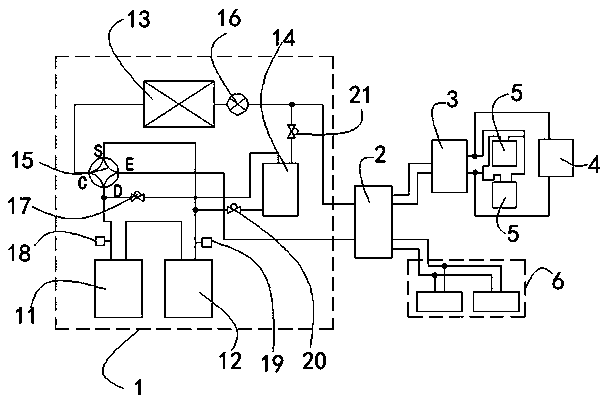
[0037] Such as figure 1 As shown, this embodiment provides a central air-conditioning system, including an air-conditioning external unit 1, a refrigerant distributor 2, a hot and cold water generator 3, a heating device 4, a fan coil unit 5, and an air-conditioning internal unit 6. Further, the air-conditioning The indoor unit 6 is any one of the air duct indoor unit, the patio indoor unit and the seat crane indoor unit. The heating device 4 is floor heating or a radiator; The cold and hot water generator 3 communicates with the fan coil unit 5 and the heating device 4 through pipes, and the air conditioner internal unit 6 is connected with the refrigerant distributor 2 through pipes.
[0038] In a preferred embodiment, the air conditioner external unit 1 includes a heat exchanger 13, a refrigerant adjustment tank 14, a gas-liquid separator 12, a compressor 11, and a four-way valve 15, and one end of the heat exchanger 13 communicates with the refrigerant distributor 2 throug...
Embodiment 2
[0059] The difference between this embodiment and Embodiment 1 is that the installation and matching method of a central air-conditioning system in this embodiment is as follows: the indoor unit of the seat crane and the floor heater (or radiator) are installed in the same room, and further, the indoor unit of the seat crane can be Choose from seat or ceiling mounts.
[0060] Under the above-mentioned installation and matching method, a control method of a central air-conditioning system includes the following steps:
[0061] Heating steps:
[0062] (1) The user turns on the machine for heating, and opens the four-way valve 15, so that D-E is connected and C-S is connected;
[0063] (2) The refrigerant evaporates in the heat exchanger 13, enters the gas-liquid separator 12 through C-S for gas-liquid separation, and then enters the compressor 11 for compression, and then enters the refrigerant distributor 2 through D-E. At this time, the heating electronic expansion valve 16 ...
Embodiment 3
[0076] The difference between the present embodiment and the first embodiment lies in that the installation and collocation of a central air-conditioning system in the present embodiment is as follows: fan coil unit 5 and floor heating (or radiator) are installed in the same room.
[0077] Under the above-mentioned installation and matching method, a control method of a central air-conditioning system includes the following steps:
[0078] Heating steps:
[0079] (1) The user turns on the machine for heating, and opens the four-way valve 15, so that D-E is connected and C-S is connected;
[0080] (2) The refrigerant evaporates in the heat exchanger 13, enters the gas-liquid separator 12 through C-S for gas-liquid separation, and then enters the compressor 11 for compression, and then enters the refrigerant distributor 2 through D-E. At this time, the heating electronic expansion valve 16 maintain a certain opening;
[0081] (3) The pressure value of the inlet valve 21 is P1,...
PUM
 Abstract
Description
Claims
Application Information
 - R&D Engineer
- R&D Manager
- IP Professional
- Industry Leading Data Capabilities
- Powerful AI technology
- Patent DNA Extraction
Browse by: Latest US Patents, China's latest patents, Technical Efficacy Thesaurus, Application Domain, Technology Topic.
© 2024 PatSnap. All rights reserved.Legal|Privacy policy|Modern Slavery Act Transparency Statement|Sitemap