Plastic particle mixing dryer

A stirring dryer and plastic granule technology, which is applied in the field of plastic manufacturing and processing, can solve the problems of poor drying effect of plastic granules, etc.

Inactive Publication Date: 2018-06-26
重庆市中塑新材料有限公司
View PDF12 Cites 12 Cited by
  • Summary
  • Abstract
  • Description
  • Claims
  • Application Information

AI Technical Summary

Problems solved by technology

[0004] The purpose of the present invention is to provide a plastic granule stirring dryer to solve the problem in the prior art that the drying effect of plastic granules is not good due to the accumulation of plastic granules and insufficient contact with hot air during the drying process.

Method used


Image

  • Plastic particle mixing dryer
  • Plastic particle mixing dryer
  • Plastic particle mixing dryer

Examples


Embodiment 1

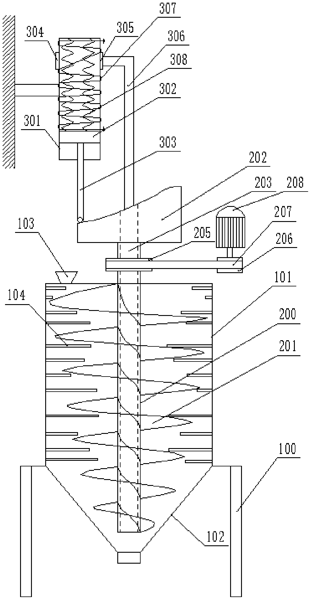
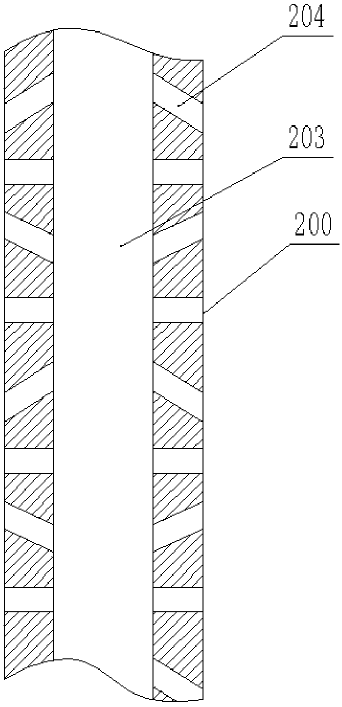
[0030] The first embodiment of the present invention is as figure 1 As shown, a plastic particle stirring dryer is disclosed, comprising a frame 100 fixed to the ground, a drying box is installed on the frame 100, the drying box includes a cylindrical material barrel 101 and a conical discharge hopper 102, and the conical discharge hopper 102 is arranged below the material barrel 101, the top of the material barrel 101 is provided with a cover, the cover is provided with a feed hopper 103 and an opening for the shaft 200 to pass through, and the top of the rotating shaft 200 exposes the material barrel 101; on the inner wall of the material barrel 101 There are a plurality of columnar protrusions 104 with different lengths, and a spiral blade 201 is provided on the rotating shaft 200 inside the barrel 101; an end cam 202 is provided on the top of the rotating shaft 200, and a through hole communicating with the end cam 202 is provided inside the rotating shaft 200 203; the rot...

Embodiment 2

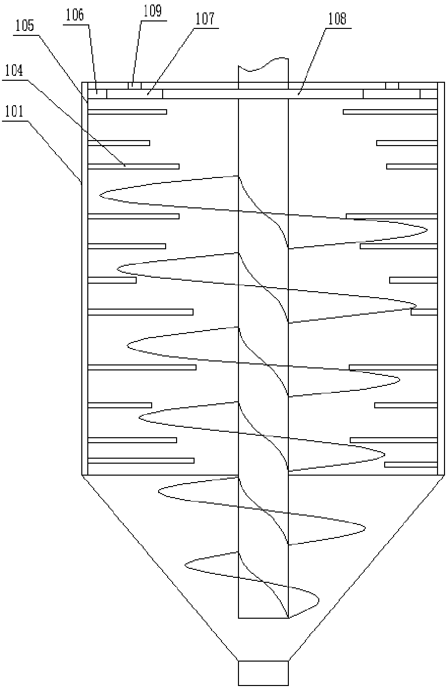
[0034] The difference from the first embodiment is that the columnar projections 104 in the second embodiment are arranged on a drum 105, such as image 3 As shown, the rotating drum 105 is meshed with the rotating shaft 200 through planetary gears, the inner wall of the rotating drum 105 is provided with a ring gear 106 near the top of the barrel 101, the sun gear 108 is installed on the rotating shaft 200, and the planet carrier 109 is connected to the top of the barrel 101. The specific connection method is as Figure 4 As shown; the rotating cylinder 105 is arranged inside the material barrel 101, and the rotating cylinder 105 is connected with the material barrel 101 in rotation, and the specific method is as follows Figure 5 As shown, an annular protrusion 110 is provided at the connection between the material barrel 101 and the discharge hopper 102, and a spherical groove is arranged on the annular protrusion 110. Several balls 111 are placed in the spherical groove, a...


PUM


Abstract

The invention belongs to the technical field of plastic manufacturing, and specifically discloses a plastic particle mixing dryer comprising a material barrel and a discharging hopper. The inner wallof the material barrel is provided with a plurality of columnar bulges, and a rotating shaft is provided with helical blades; the top of the rotating shaft is provided with an end cam, and the rotating shaft and the end cam are internally provided with through holes which communicate with each other; the side wall of the rotating shaft in the material barrel is provided with air outlets which communicate with the through holes; a support frame is provided with a cylinder, and the lower end face of an ejector rod in the cylinder abuts against the concave side of the end cam; a coil is wound onthe outer wall of the cylinder, and connected to an AC motor; and the outer wall of the cylinder is provided with a one-way air inlet valve and a one-way air outlet valve, and a hot air pipe communicating with the through holes is installed between the one-way air outlet valve and the end cam. According to the technical scheme, hot air is intermittently discharged into a drying oven through the quick reciprocating motion of a cylinder piston, so that plastic particles are switched between two motion states, namely irregular movement and falling-down, and the plastic particles are mixed thoroughly.

Description

technical field [0001] The invention belongs to the technical field of plastic manufacturing and processing, and in particular relates to a mixing dryer for plastic particles. Background technique [0002] Starting from the synthesis of plastics, almost all thermoplastics have to go through the process of granulation. In addition to new materials that need to be granulated, dyeing, filling, reinforcement, and waste recycling in processing and production all need to be re-granulated. Traditional granulation technology There are two methods of hot granulation and cold granulation. During the plastic granulation process, in order to prevent the plastic granules from being deformed or melted due to excessive temperature, cold water is often used for cooling treatment. Therefore, drying operation is required after the granulation is completed. There are many factors that affect the drying effect of plastic particles, including drying temperature, drying time and air flow, etc.; h...

Claims


Application Information

Patent Timeline
Patent Type & Authority Applications(China)
IPC IPC(8): F26B17/22F26B21/00F26B25/16
CPCF26B17/22F26B21/001F26B21/004F26B25/16F26B2200/08
Inventor 李兴斌
Owner 重庆市中塑新材料有限公司
Why Eureka
Try Eureka