Cloth drying device

A cloth drying and supporting device technology, applied in drying, drying machine, drying gas arrangement, etc., can solve the problems of cloth quality reduction, cloth waste, easy to mold, etc.

Inactive Publication Date: 2020-02-07
JIANGSU LIBO TEXTILE
View PDF0 Cites 0 Cited by
  • Summary
  • Abstract
  • Description
  • Claims
  • Application Information

AI Technical Summary

Problems solved by technology

[0003] The purpose of the present invention is to provide a cloth drying device, which solves the problem that the cloth with moisture in the prior art is prone to mildew during long-term storage, resulting in a decrease in the quality of the cloth, resulting in waste of the cloth and increasing the production cost.

Method used


Image

  • Cloth drying device
  • Cloth drying device
  • Cloth drying device

Examples


Embodiment

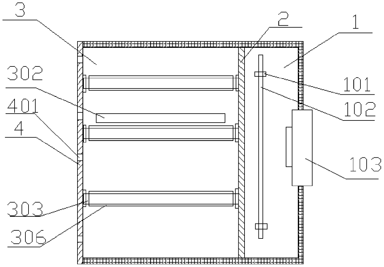
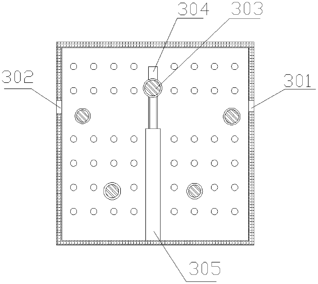
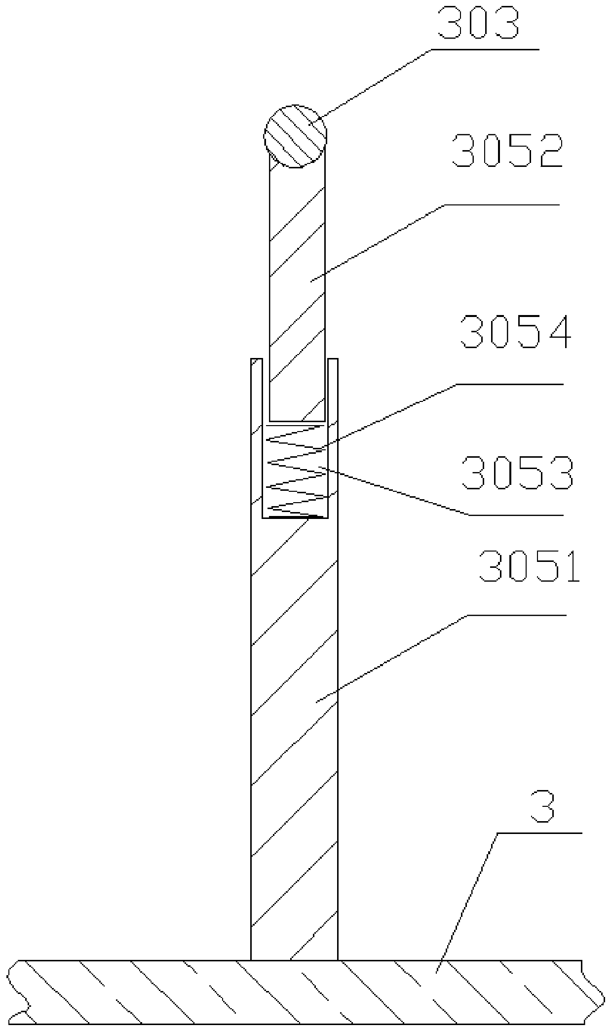
[0017] Example: such as figure 1 , figure 2 and image 3 As shown, a cloth drying device includes a heating box 1, a ventilation plate 2 and a drying box 3, the drying box 3 is located on the outside side of the heating box 1, and the heating box 1 and the drying box The body 3 is connected through the ventilation plate 2, the ventilation plate 2 is provided with a ventilation hole 201, the inner wall of the heating box 1 is provided with a fixed block 101, and the electric heating tube 102 is installed on the fixed block 101, and the electric heating tube 102 is electrically connected to the control panel of the peripheral equipment. The other side of the heating box 1 is provided with a fan 103, the air inlet of the fan 103 is located outside the heating box 1, the air outlet of the fan 103 is located inside the heating box 1, and the fan 103 is electrically connected to the control panel of the peripheral Connection, the relative setting of the air outlet of fan 103 and ...


PUM


Abstract

The invention relates to a cloth drying device which includes a heating box, a ventilation plate and a drying box. The drying box is arranged above the heating box, the heating box and the drying boxare connected through the ventilation plate, the top of the inner wall of the heating box is provided with a fixed block, an electric heating pipe is installed on the fixed block, the electric heatingpipe is electrically connected to an externally-provided control panel, the bottom of the heating box is provided with a fan, an air inlet of the fan is located in the exterior of the heating box, anair outlet of the fan is located inside the heating box, and the fan is electrically connected to the externally-provided control panel; and the air outlet of the fan is located below the electric heating pipe, a cloth inlet slot is formed in the left end surface of the drying box, a cloth outlet slot is formed in the right end surface of the drying box, cloth guide rollers are arranged between the inner walls of the front and back ends of the drying box, cloth guide wheels are arranged on the cloth guide rollers, and the upper end face of the drying box is provided with an air outlet plate.The device is high in practicability and high in drying efficiency.

Description

technical field [0001] The invention belongs to the field of textile equipment, in particular to a cloth drying device. Background technique [0002] With the development of the economy, people's demand for textile products is increasing. In the fabric processing process, the fabric needs to be dried. The current fabric drying device cannot evenly dry the fabric. The fabric with moisture is prone to mildew during long-term storage, resulting in a decrease in the quality of the fabric. , causing the waste of cloth and increasing the production cost. Contents of the invention [0003] The purpose of the present invention is to provide a cloth drying device, which solves the problem that the cloth with moisture in the prior art is prone to mildew during long-term storage, resulting in a decrease in the quality of the cloth, resulting in waste of the cloth and increasing the production cost. . [0004] In order to solve the problems of the technologies described above, the ...

Claims


Application Information

Patent Timeline
Patent Type & Authority Applications(China)
IPC IPC(8): F26B13/14F26B21/00F26B21/08F26B25/08
CPCF26B13/14F26B21/00F26B21/08F26B25/08
Inventor 钮娟芬吴新富施勇张赛朱婷陈晨陈建军赵星星
Owner JIANGSU LIBO TEXTILE
Why Eureka
Try Eureka