Free falling body teaching experiment device
An experimental equipment and free fall technology, applied in the field of physical dynamics education demonstration equipment, can solve problems such as affecting the experimental results and mutual interference in the falling process of objects, and achieve the effect of reducing the propagation medium, avoiding mutual interference and reducing noise.
- Summary
- Abstract
- Description
- Claims
- Application Information
AI Technical Summary
Problems solved by technology
Method used
Image
Examples
Embodiment 1
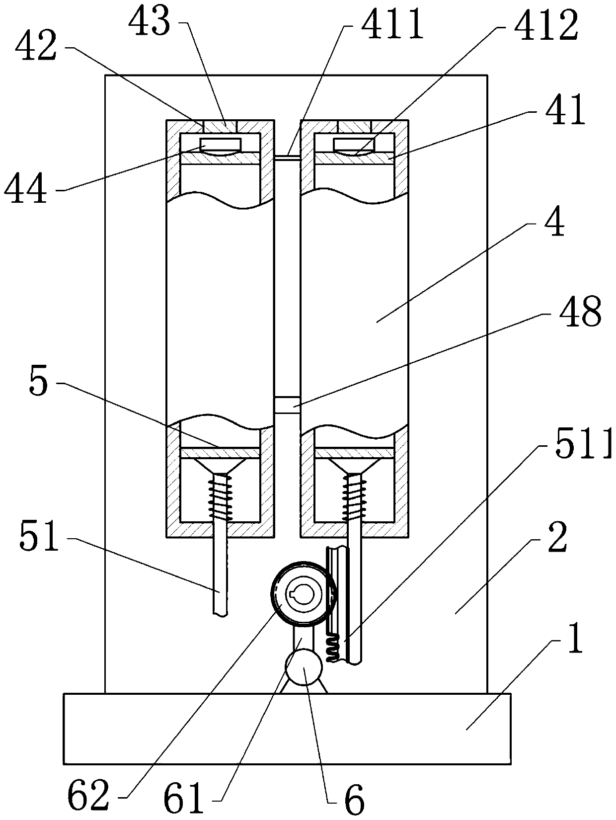
[0036] A free fall teaching experiment equipment, basically as attached figure 1 As shown, it includes a base 1, a frame 2 fixed on the base 1, and a bracket 3, and the bracket 3 is located on the rear side of the frame 2. Two closed experimental tube bodies 4 are fixed side by side on the front side of the frame body 2, and a connecting tube 48 is arranged between the experimental tube bodies 4. The two ends of the connecting tube 48 are respectively connected with the two experimental tube bodies 4, The cross section is rectangular, and the front side of the experimental tube body 4 is transparent, such as glass.
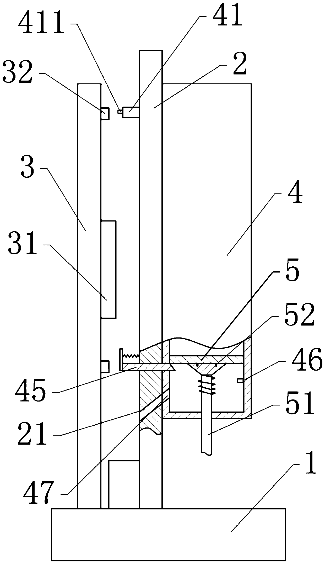
[0037] Also includes two baffles 41, combined figure 2 As shown, two baffles 41 both penetrate the back side of the frame body 2 and the experimental tube body 4 (ie figure 2 The left side of the middle), and the two pieces are connected to the frame body 2 and the experimental tube body 4 slidingly and laterally. The rear end of the baffle 41 is located on the rea...
Embodiment 2
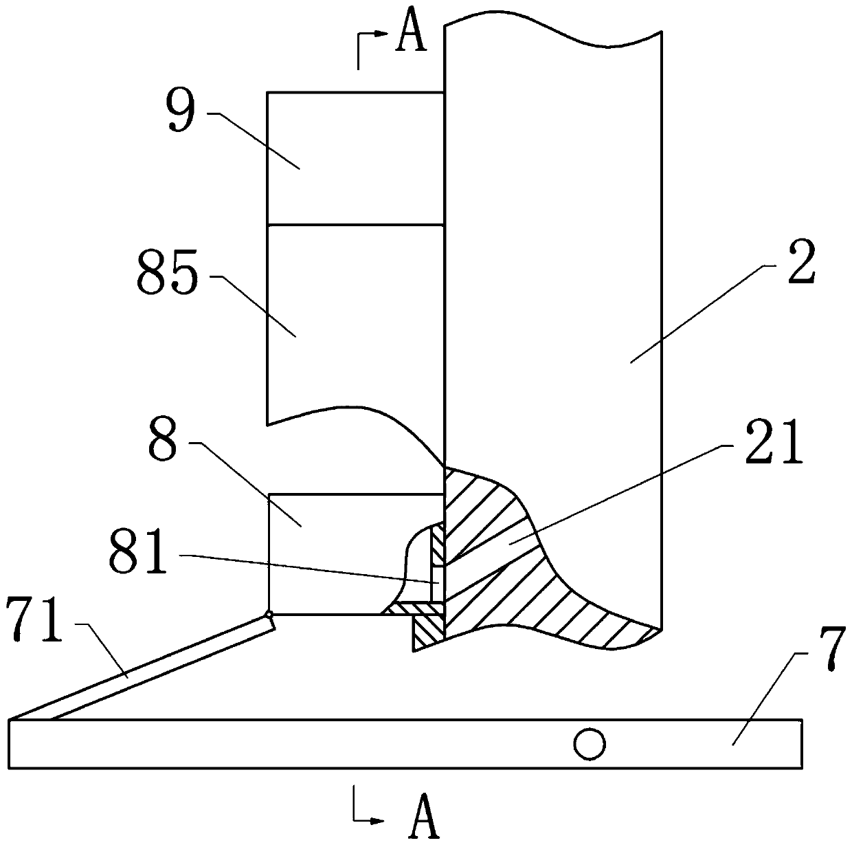
[0048] The difference between Embodiment 2 and Embodiment 1 is only that the frame body 2 is provided with a mounting groove under the test tube body 4. Such as image 3 As shown, it also includes two feeding structures, each of which includes a lever 7 hinged in the mounting groove. The distance from the left end of the lever 7 to the hinge joint with the mounting groove is three times the distance from the right end of the lever 7 to the hinge joint with the mounting groove. The right end of the lever 7 is located below the push rod 51, the left end of the lever 7 is located between the frame body 2 and the bracket 3, and the left end of the lever 7 is hinged with a moving rod 71.
[0049] To image 3 As shown in the figure, the left side of the frame body 2 is vertically slidably connected with a transport frame 8, and the top end of the moving rod 71 is hinged under the transport frame 8. The right side wall of the transport frame 8 is provided with a communication hole 81 co...
PUM
 Abstract
Description
Claims
Application Information
 - R&D
- Intellectual Property
- Life Sciences
- Materials
- Tech Scout
- Unparalleled Data Quality
- Higher Quality Content
- 60% Fewer Hallucinations
Browse by: Latest US Patents, China's latest patents, Technical Efficacy Thesaurus, Application Domain, Technology Topic, Popular Technical Reports.
© 2025 PatSnap. All rights reserved.Legal|Privacy policy|Modern Slavery Act Transparency Statement|Sitemap|About US| Contact US: help@patsnap.com


