Clamper for robot paintbrush

A technology of robots and clamps, applied to instruments, educational tools, teaching models, etc., can solve problems such as breaking, shrinkage, and inaccurate motion track data, and achieve the effect of quick disassembly

Active Publication Date: 2021-07-13
NANNING UNIV
View PDF11 Cites 0 Cited by
  • Summary
  • Abstract
  • Description
  • Claims
  • Application Information

AI Technical Summary

Problems solved by technology

[0002] In the process of robot development or teaching research and development experiments, it is necessary to test the movement trajectory of the robot arm, and then verify the robot itself or the source code of the robot control according to the movement trajectory data; in order to obtain the movement trajectory data, generally use a pencil or The marker pen is fixed on the robot and moves on the drawing board to obtain the motion trajectory data. Due to the natural vibration of the robot during motion, the tip of the pencil breaks on the drawing board or the tip of the marker pen shrinks inward on the drawing board, resulting in movement Inaccurate track data
[0003] The Chinese patent publication CN107808581A discloses a fixture for teaching industrial robots. The disclosed technical solution is "the spring is arranged between the outer cylinder and the inner cylinder, ... the thin end of the inner cylinder is provided with a radial The screw hole is used to fix the marker pen to the inner cavity of the inner cylinder through the fastening screw matched with the radial screw hole", although the technical solution can make the pencil or marker pen in the state perpendicular to the drawing board. The natural vibration of the robot It will be slowed down on the spring, but when the pencil or marker and the drawing board are used in an inclined state, due to the hard contact between the outer cylinder and the inner cylinder, the tip of the pencil is still broken on the drawing board or the tip of the marker is still on the drawing board. indentation problem

Method used


Image

  • Clamper for robot paintbrush
  • Clamper for robot paintbrush
  • Clamper for robot paintbrush

Examples


Embodiment Construction

[0026] The technical solution of the present invention is further described below, but the scope of protection is not limited to the description.

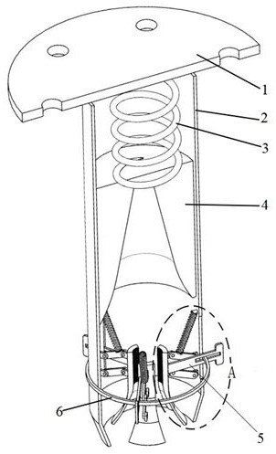
[0027] see figure 1 , figure 2 , image 3 , Figure 4 .

[0028] A clamper for a robot paintbrush according to the present invention comprises a flange cover 1;

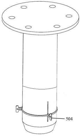
[0029] Pen container 2, the top surface of the pen container 2 is welded or bonded to the bottom surface of the flange cover 1;

[0030] Spring A3, sleeve 4, and sleeve 4 are slidably installed inside the pen container 2, and the two ends of spring A3 are respectively in contact with or bonded to flange cover 1 and sleeve 4, and the middle part of sleeve 4 is provided with a tapered mounting bracket for paintbrush 7. hole;

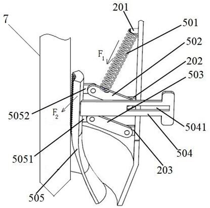
[0031] A plurality of buffer clamping mechanisms 5, a plurality of buffer clamping mechanisms 5 for clamping a paintbrush 7 are fixedly installed on the bottom of the pen holder 2.

[0032] In order to realize the buffering and clamping functi...


PUM


Abstract

The invention discloses a gripper for a robot paintbrush, comprising a flange cover; a pen holder, the top surface of the pen holder is welded or fixedly connected with the bottom surface of the flange cover; a spring A, a sleeve, and the sleeve can be slidably mounted on Inside the pen barrel, the two ends of the spring A are in contact with or bonded to the flange cover and the sleeve respectively, and the middle of the sleeve is provided with a conical hole for the installation of the brush; a plurality of buffer clamping mechanisms are fixedly installed at the bottom of the pen barrel to clamp the brush. Buffer clamping mechanism. When the brush is in inclined contact with the drawing board during use, the radial component force of the drawing board on the brush will be offset by the spring B on the buffer clamping mechanism, which solves the problem that the brush tip of the pencil is broken on the drawing board or the brush is used. The problem that the tip of the marker is retracted on the drawing board. The synchronizing ring drives the lever to move upwards synchronously, further drives the clamping blocks to move upwards, and simultaneously opens the plurality of clamping blocks to realize the quick disassembly of the brush.

Description

technical field [0001] The invention belongs to the technical field of robot clamps, and relates to a clamper for a robot brush. Background technique [0002] In the process of robot development or teaching research and development experiments, it is necessary to test the movement trajectory of the robot arm, and then verify the robot itself or the source code of the robot control according to the movement trajectory data; in order to obtain the movement trajectory data, generally use a pencil or The marker pen is fixed on the robot and moves on the drawing board to obtain the motion trajectory data. Due to the natural vibration of the robot during motion, the tip of the pencil breaks on the drawing board or the tip of the marker pen shrinks inward on the drawing board, resulting in movement Track data is inaccurate. [0003] The Chinese patent publication CN107808581A discloses a fixture for teaching industrial robots. The disclosed technical solution is "the spring is arr...

Claims


Application Information

Patent Timeline
Patent Type & Authority Patents(China)
IPC IPC(8): G09B25/02
CPCG09B25/02
Inventor 黄才贵何宇
Owner NANNING UNIV
Why Eureka
Try Eureka