Flange type angle lock device and display screen module

A display module and flange-type technology, applied in the direction of identification devices, instruments, etc., can solve the problems of low transportation efficiency, large assembly clearance, and difficulty in the versatility of parts, so as to achieve convenient and quick assembly, improve assembly accuracy, The effect of improving assembly quality

Pending Publication Date: 2020-02-07
SHENZHEN UNIVIEW LED
View PDF0 Cites 3 Cited by
  • Summary
  • Abstract
  • Description
  • Claims
  • Application Information

AI Technical Summary

Problems solved by technology

[0003] However, large-size display screens and multi-model display screens are difficult to realize in terms of technology and the transportation efficiency in product transportation is not high. It has always been a pain point in the industry.
The current popular technology is to divide the large-size display into multiple small-size display modules, manufacture the small-size modules in the factory with the existing technology, and then transport the small-size modules to the installation site according to the large-size The design of the display screen requires splicing, which solves the problems that the large-size display screen is not easy to realize in technology and the transportation efficiency is low
[0004] In industrial practice, spliced ​​large-size display screens need to be tightly and securely connected and locked each component module. For flat-screen display screens, there are many locking methods in the prior art that can meet the design and installation requirements. If the screen is a curved surface (or curved surface) or a multi-shaped surface, it is necessary to design a special locking device according to the design curvature or shape of the display screen, which increases the design difficulty of large-size multi-shaped display screens and causes product parts Versatility Difficulties
[0005] Although there are universal multi-angle locking devices on the market, it still cannot eliminate the relatively large assembly gap and ensure the high-precision assembly requirements required by the design.

Method used


Image

  • Flange type angle lock device and display screen module
  • Flange type angle lock device and display screen module
  • Flange type angle lock device and display screen module

Examples


Embodiment Construction

[0025] In order to explain the technical solution of the present invention more clearly, the embodiments of the present invention will be briefly described below in conjunction with the accompanying drawings. Obviously, the description of the embodiments and the accompanying drawings is only to illustrate the technical solutions of the present invention. Under the background that those of ordinary skill in the art can understand, the scope of protection of the present invention is not limited to the embodiments and accompanying drawings.

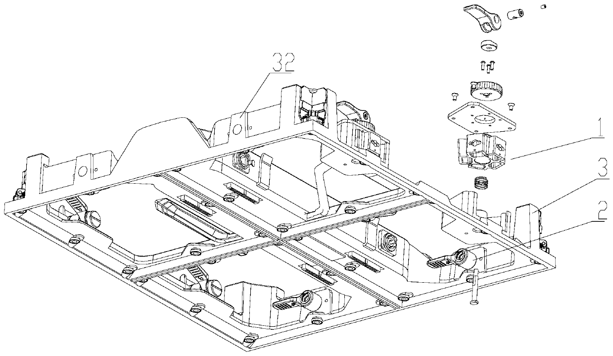
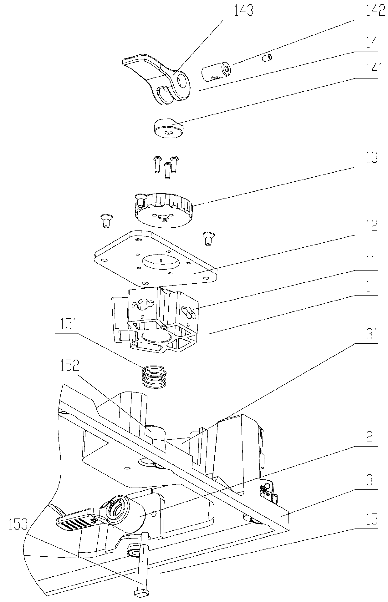
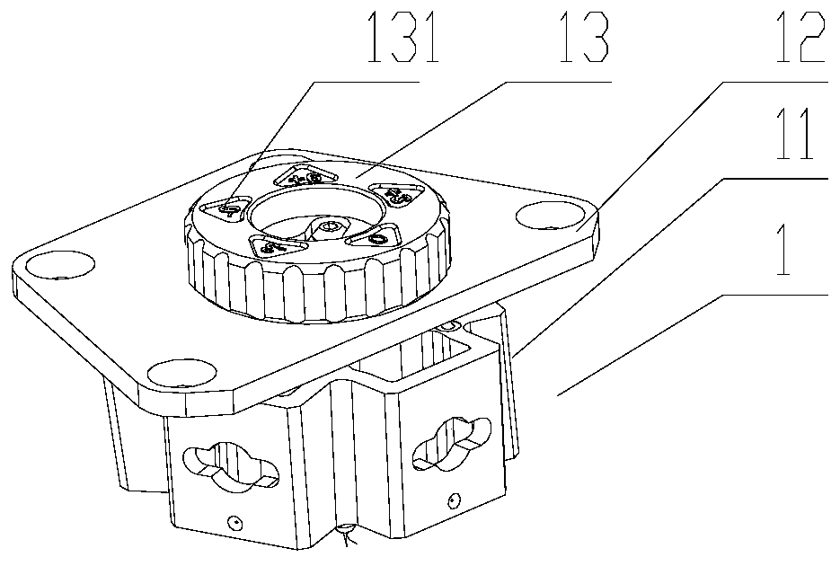
[0026] Such as figure 1 , 2 As shown, a flange-type angle lock device is installed on the LED display module frame 3. The flange-type angle lock device includes a lock cylinder assembly 1 and a quick lock that cooperates with the lock cylinder assembly 1 to lock Component 2, the "fitting and locking" mentioned here means that when multiple LED display modules are assembled, the lock cylinder assembly 1 on one LED display module is installed...


PUM


Abstract

The invention provides a flange type angle lock device. The flange type angle lock device comprises a lock cylinder assembly and a quick lock assembly which is matched and locked with the lock cylinder assembly; the lock cylinder assembly comprises an angle turning core, a turning core cover plate fixedly connected with the angle turning core, an angle adjusting knob fixedly connected with the turning core cover plate, and a compression locking device installed in the angle adjusting knob, wherein the turning core cover plate is located between the angle turning core and the angle adjusting knob; the angle adjusting knob is located between the turning core cover plate and the compression locking device; and the lock cylinder assembly further comprises a positioning and mounting assembly connected with the angle turning core. By using the technical scheme provided by the invention, not only the rapid splicing and locking of a display screen module is realized, but no tools are needed inthe entire splicing process, so that the splicing process is simplified while the splicing precision is improved, and the cost of the product is also saved.

Description

technical field [0001] The invention relates to the technical field of locking connection, in particular to a technical field for splicing and locking of LED display modules. Background technique [0002] The LED display industry is developing rapidly, and the application fields are constantly expanding. The development trend of this industry is constantly approaching large screens and super large screens, and the traditional flat screens can no longer meet the growing demand of the market. More and more curved screens or multi-shaped screens The development of the screen is put on the agenda. [0003] However, large-size display screens and multi-model display screens are not easy to realize in terms of technology and the transportation efficiency in product transportation is not high, which has always been a pain point in the industry. The current popular technology is to divide the large-size display into multiple small-size display modules, manufacture the small-size mo...

Claims


Application Information

Patent Timeline
Patent Type & Authority Applications(China)
IPC IPC(8): G09F9/33
CPCG09F9/33
Inventor 黄勇奇吴晶郭畅
Owner SHENZHEN UNIVIEW LED
Why Eureka
Try Eureka