
Network camera control device

A network camera and control equipment technology, applied in the field of camera, can solve the problems of camera influence, unreliable fixing method of network camera, speeding up of signal processor, etc., and achieve the effect of reducing the depth of field, highlighting the subject, and blurring the background

Inactive Publication Date: 2020-02-07
陈洪群
View PDF10 Cites 0 Cited by
  • Summary
  • Abstract
  • Description
  • Claims
  • Application Information

AI Technical Summary

Problems solved by technology

[0004] The purpose of the present invention is to provide a network camera in order to solve the problems (the fixation of the camera itself affects the omnidirectional video recording of the monitor, the unreliable fixing method of the network camera and the lack of a signal processor to speed up the information transmission of data). controlling device

Method used


Image

  • Network camera control device
  • Network camera control device
  • Network camera control device

Examples


Embodiment Construction

[0034] In order to make the object, technical solution and advantages of the present invention clearer, the present invention will be further described in detail below in conjunction with the accompanying drawings and embodiments. It should be understood that the specific embodiments described here are only used to explain the present invention, not to limit the present invention.

[0035] In the description of the present invention, it should be noted that the terms "center", "upper", "lower", "left", "right", "vertical", "horizontal", "inner", "outer" etc. The indicated orientation or positional relationship is based on the orientation or positional relationship shown in the drawings, and is only for the convenience of describing the present invention and simplifying the description, rather than indicating or implying that the referred device or element must have a specific orientation, or in a specific orientation. construction and operation, and therefore cannot be constru...


PUM


Abstract

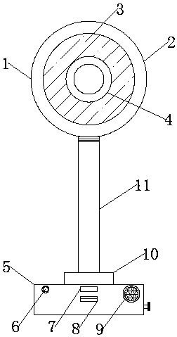
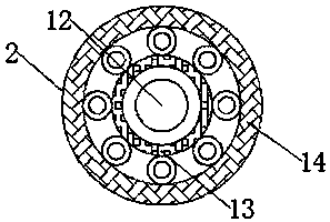
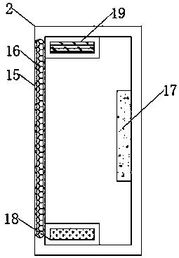
The invention discloses a network camera control device, comprising a device main body, a camera device, a device base and a connecting device, wherein the top of the device main body is movably connected with the camera device; the bottom of the device main body is fixedly connected with the device base; the top of the device base is fixedly connected with the connecting device; the middle part of a transparent protective layer is fixedly connected with an aperture; one side of the front of the device base is fixedly connected with a power indicator; a transparent protective layer is connected to the front surface of the camera device in an embedded manner; the transparent protective layer reflects the protectiveness of the device; the aperture reflects the monitoring accuracy of the device; the power supply indicating lamp reflects the warning property of the device; the recorder reflects the monitoring comprehensiveness of the device; the camera device reflects the efficiency and convenience of signal processing of the device; and the device base reflects the fixity and detachability of the device, and the connecting device reflects the adjustability of the monitoring angle of the device, is suitable for being used by the network camera control device, and has a wide development prospect in the future.

Description

technical field [0001] The invention belongs to the technical field of cameras, in particular to a network camera control device. Background technique [0002] A camera is a machine that converts optical image signals into electrical signals for storage or transmission. When we shoot an object, the light reflected on the object is collected by the camera lens to focus on the light-receiving surface of the camera. Then the light is converted into electrical energy through the camera, and the "video signal" is obtained. The photoelectric signal is very weak and needs to be amplified by the pre-amplification circuit, and then processed and adjusted by various circuits. The final standard signal can be sent to the video recorder. Recorded on the recording medium, or transmitted through the communication system or sent to the monitor for display. [0003] However, the existing network camera cannot automatically rotate the lens during the operation of the monitor, which is incon...

Claims


Application Information

Patent Timeline
IPC IPC(8): H04N5/225H04N7/18
CPCH04N7/18H04N23/00
Inventor 不公告发明人
Owner 陈洪群
Learn More