Device internal and external surface integrated imaging method

A technology of internal and external surfaces and imaging methods, applied in the field of imaging, can solve problems such as complex process of machine vision equipment, complex equipment maintenance, and lengthy production cycle, and achieve the effects of reducing the depth of field of the lens, increasing the clarity, and simplifying the complexity of the device

Pending Publication Date: 2020-08-04
长沙麦睛科技股份有限公司
View PDF9 Cites 0 Cited by
  • Summary
  • Abstract
  • Description
  • Claims
  • Application Information

AI Technical Summary

Problems solved by technology

Under such circumstances, the cost of production is high and the production process of machine vision equipment is more complicated, the production cycle of the product is more lengthy, and the final produced machine vision equipment also has multiple sets of imaging equipment, the stability of production will be relatively Single set of imaging system equipment reduces
It will also be more complex in terms of equipment maintenance

Method used


Image

  • Device internal and external surface integrated imaging method
  • Device internal and external surface integrated imaging method
  • Device internal and external surface integrated imaging method

Examples


Embodiment

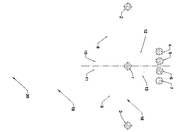
[0038] see Figure 1-5 , the present embodiment provides an integrated imaging method for the inner and outer surfaces of a device, comprising the following steps:

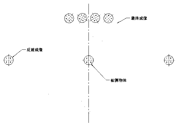
[0039] The first piece 1 is a test sample that can flow horizontally on the production line 18. When the first piece 1 flows from right to left on the production line to the middle of the imaging device, the light source 19 will illuminate the object;

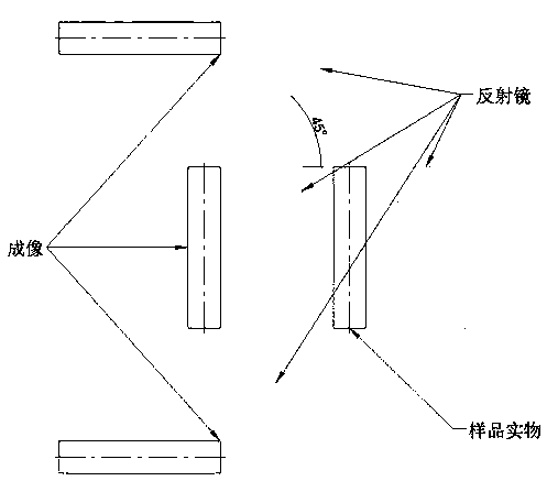
[0040] The eighth piece 8 and the ninth piece 9 are two left and right reflectors, which reflect to form two images of the second image 2 and the third image 3;

[0041] The second image 2 and the third image 3 form the fifth image 5 and the sixth image 6 by the tenth piece 10 and the eleventh piece 11 mirrors;

[0042] The first piece 1 forms the fifth image 5 and the sixth image 6 by the twelfth piece 12 and the thirteenth piece 13;

[0043] The top of the first piece 1 forms the sixteenth image 16 by the fourteenth piece 14, and generates the seventeenth image...


PUM


Abstract

The invention discloses a device internal and external surface integrated imaging method. The method comprises the steps of setting an eighth part and a ninth part as a left reflector and a right reflector respectively, and forming a second image and a third image through reflection; forming the second image and the third image into a fifth image and a sixth image through a tenth reflecting mirrorand an eleventh reflecting mirror; forming the first part into a fifth image and a sixth image through a twelfth part and a thirteenth part; forming a sixteenth image at the top of the first part through a fourteenth part, and generating a seventeenth image through a fifteenth part; controlling the angles of the eighth part, the ninth part, the tenth part, the eleventh part, the twelfth part, thethirteenth part, the fourteenth part and the fifteenth part, so that all image planes needing to be measured can be located on the same plane. The method is wide in application range, and multi-surface and multi-angle imaging, shooting and measurement can be performed on most measured objects by designing different sizes and angles of the reflector groups.

Description

technical field [0001] The invention relates to the field of imaging technology, in particular to an integrated imaging method for the inner and outer surfaces of a device. Background technique [0002] During the operation of machine vision projects, it is often encountered that multiple sides of the product need to be imaged for related inspections. In this case, multiple imaging systems are required to image different surfaces of the object. Imaging results are crucial to machine vision analysis results. It also restricts the cost and use effect of finished machinery. [0003] In general, multiple imaging systems, multiple light sources, and imaging tools such as camera lenses are often required for multi-faceted imaging of objects. And the performance requirements of the computer are more stringent. Under such circumstances, the cost of production is high and the production process of machine vision equipment is more complicated, the production cycle of the product i...

Claims


Application Information

Patent Timeline
Patent Type & Authority Applications(China)
IPC IPC(8): G01N21/88B07C5/342G03B15/06G03B30/00
CPCG01N21/8806B07C5/342G03B15/06G01N2021/8809
Inventor 谢纪东刘晓春包崇兵
Owner 长沙麦睛科技股份有限公司
Why Eureka
Try Eureka