Fire fighting cabinet

A technology for fire cabinets and fire extinguishers, applied in fire rescue and other directions, can solve the problems of inability to spray fire extinguishing agent, inability to roll up water pipes, and difficulty in taking and storing fire extinguishers, achieving the effect of convenient storage and utilization of storage space

Active Publication Date: 2020-02-11
山东亚泰新材料科技有限公司
View PDF7 Cites 3 Cited by
  • Summary
  • Abstract
  • Description
  • Claims
  • Application Information

AI Technical Summary

Problems solved by technology

[0002] In fire protection engineering, the fire cabinet is one of the necessary equipment. The fixed fire extinguishers in the traditional fire cabinet

Method used


Image

  • Fire fighting cabinet
  • Fire fighting cabinet
  • Fire fighting cabinet

Examples


specific Embodiment approach 1

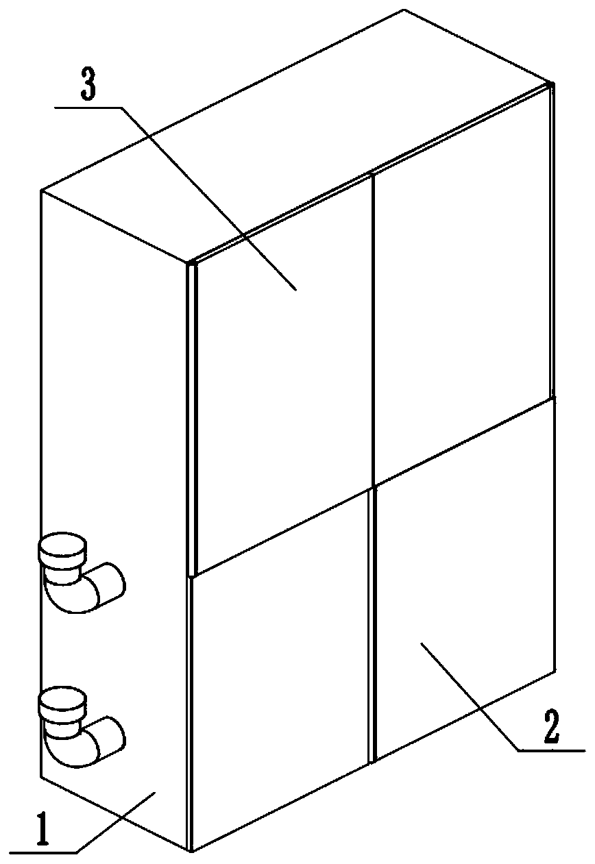
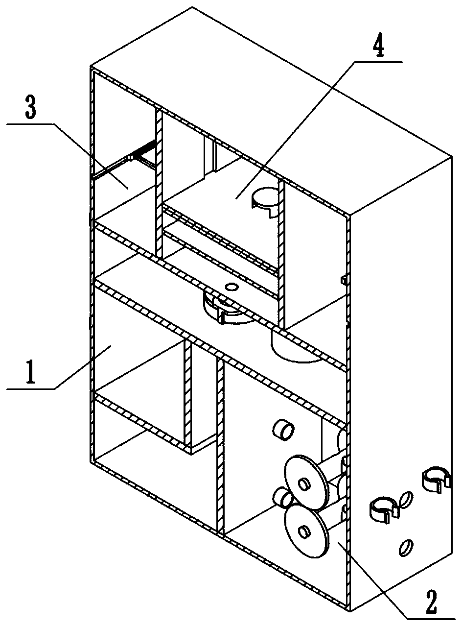
[0033] Combine below Figure 1-18 In this embodiment, a fire fighting cabinet includes a liquid storage assembly 1, a coiled tube assembly 2, a fire extinguisher clamping assembly 3, and a storage assembly 4. It is characterized in that: the coiled tube assembly 2 and the liquid storage The assembly 1 is connected, the fire extinguisher clamping assembly 3 is connected with the liquid storage assembly 1, and the storage assembly 4 is connected with the liquid storage assembly 1.

specific Embodiment approach 2

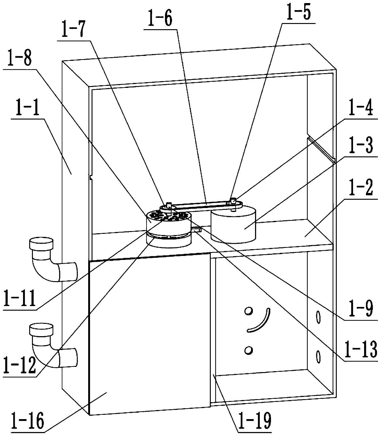
[0035] Combine below Figure 1-18This embodiment, this embodiment will further explain the first embodiment, the liquid storage assembly 1 includes a fire cabinet 1-1, a horizontal frame 1-2, a motor I1-3, a motor I shaft 1-4, and a sprocket I1 -5, chain Ⅰ1-6, sprocket Ⅱ1-7, fan housing 1-8, fan blade shaft 1-9, fan blade 1-10, air inlet 1-11, switch lever chute 1-12, switch lever 1 -13, switching shaft 1-14, windshield 1-15, box door 1-16, box Ⅰ side plate 1-17, box Ⅰ bottom plate 1-18, box Ⅱ side plate 1-19, water pipe Ⅰ 1-20, Water pipe Ⅱ1-21, curved groove 1-22, water inlet pipe 1-23, end cover 1-24, box Ⅰ1-25 and box Ⅱ1-26, horizontal frame 1-2 is connected with fire cabinet 1-1, motor Ⅰ1- 3 is connected with the horizontal frame 1-2, the motor I1-3 is connected with the motor I shaft 1-4, the motor I shaft 1-4 is connected with the sprocket I1-5, the sprocket I1-5, the chain I1-6, The sprocket Ⅱ1-7 is connected by a sprocket chain, the sprocket Ⅱ1-7 is connected with t...

specific Embodiment approach 3

[0037] Combine below Figure 1-18 This embodiment, this embodiment will further explain the first embodiment, the coiled tube assembly 2 includes the sliding door I2-1, the motor II bracket 2-2, the motor II2-3, the motor II shaft 2-4, and the gear I2 -5, friction block 2-6, gear II 2-7, rotary rod 2-8, gear II shaft 2-9, gear III 2-10, reel shaft 2-11, friction groove 2-12, reel 2-13 , pipe hole Ⅰ2-14, faucet clip 2-15 and pipe hole Ⅱ2-16, the sliding door Ⅰ2-1 is hinged with the box Ⅱ side panel 1-19, the motor Ⅱ bracket 2-2 is connected with the fire cabinet 1-1 rear panel , motor II 2-3 is connected with motor II bracket 2-2, motor II 2-3 is connected with motor II shaft 2-4, motor II shaft 2-4 is rotationally connected with fire cabinet 1-1 rear plate, motor II shaft 2 The two friction grooves 2-12 on -4 are in contact with the two friction blocks 2-6 respectively, and the two friction blocks 2-6 are respectively connected with the gear I 2-5 and the rotary rod 2-8, and ...


PUM


Abstract

The invention belongs to the field of fire fighting, and particularly relates to a fire fighting cabinet. A fire fighting cabinet is one of necessary equipment in fire fighting engineering. Accordingto the fire fighting cabinet, the problems that a fixed fire extinguisher of a traditional fire fighting cabinet is not easy to take and store, then the use space cannot be adjusted according to stored objects, two different fire extinguishing agents cannot be sprayed, and water pipes cannot be rolled up automatically are solved; and the fire extinguishing agents in two liquid storage tanks are adjusted to be respectively sprayed or simultaneously sprayed by switching a switching rod, winding drums can be controlled to roll up the water pipes by adjusting the steering of a motor, then the fireextinguishers with different shapes can be clamped, the fire extinguishers are convenient to take and store, the fire extinguishers cannot be dumped, the use space of storage lattices can be adjusted, and thus the storage space can be utilized to the greatest extent.

Description

technical field [0001] The invention relates to the field of fire fighting, more specifically to a fire fighting cabinet. Background technique [0002] In fire protection engineering, the fire cabinet is one of the necessary equipment. The fixed fire extinguishers in the traditional fire cabinet are not easy to take and store, and the use space cannot be adjusted according to the stored items. From now on, this device solves the above-mentioned problems. Contents of the invention [0003] The purpose of the present invention is achieved through the following technical solutions: [0004] A fire extinguishing cabinet, comprising a liquid storage assembly, a coiled tube assembly, a fire extinguisher clamping assembly, and a storage assembly, the coiled tube assembly is connected to the liquid storage assembly, and the fire extinguisher clamping assembly is connected to the liquid storage assembly The combination is connected, and the storage combination is connected with t...

Claims


Application Information

Patent Timeline
IPC IPC(8): A62C35/20A62C31/07A62C33/04
CPCA62C31/07A62C33/04A62C35/20
Inventor 杨华亮王生
Owner 山东亚泰新材料科技有限公司
Why Eureka
Try Eureka