
Eureka
For R&D, Eureka makes reading and utilizing patents & technical documents easy.
Eureka AIR
Designed for self-driven R&D workflows. Generate viable solutions, solve complex R&D challenges, empower your innovation with AI.

Eureka Materials
Designed for material experts only. Revolutionize your material R&D, from search, analyze, to developing new materials.

TechResearch
Generate reliable direction feasibility study reports for your R&D in just a few steps.

TechSeek
Discover and master advanced knowledge NOW. Basics, ideas, possibilities, all at once.

TechMind
As an expert in R&D Theories, TechMind can generates customized viable solutions instantly.

TechRisk
Analyze your overall solution with one click, know your potential R&D risks in advance.

TechMonitor
Get weekly tech updates, stay abreast of the latest tech innovations and key insights.
Recording device, image processing device and recording method
A technology for recording devices and image data, applied in the directions of image communication, printing, electrical components, etc., can solve problems such as point position deviation, reduction, and hinder cost reduction.
- Summary
- Abstract
- Description
- Claims
- Application Information
AI Technical Summary
Problems solved by technology
Method used
Image

Examples
Embodiment approach 1
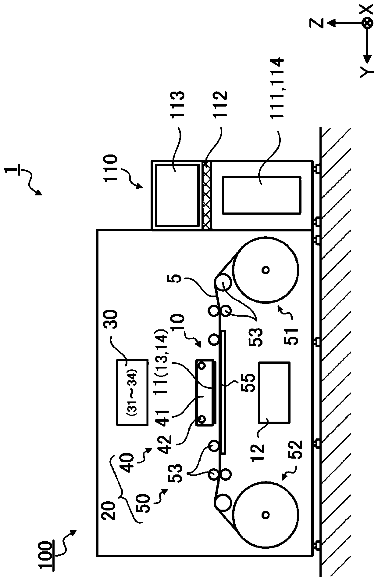
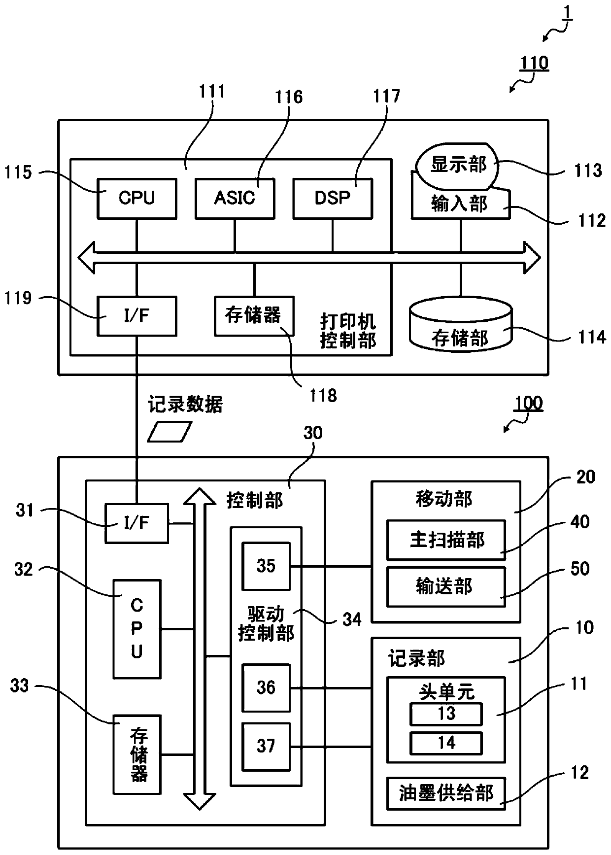
[0043] figure 1 It is a front view showing the configuration of a recording system 1 as a "recording device" according to Embodiment 1, figure 2 its block diagram.
[0044] The recording system 1 is constituted by a printer 100 and an image processing apparatus 110 connected to the printer 100 . The printer 100 is an inkjet printer that records a desired image on a long recording medium 5 supplied in a state of being wound into a roll, based on recording data received from the image processing apparatus 110 .
[0045] As the recording medium 5, high-quality paper, cast paper, art paper, coated paper, synthetic paper, etc. can be used, for example. In addition, the recording medium 5 is not limited to this kind of paper, for example, a cloth, a film made of PET (Polyethyleneterephthalate: polyethylene terephthalate), PP (polypropylene: polypropylene), or the like can be used. In addition, in this embodiment, the case where the recording surface of the recording medium 5 is ...
Embodiment 1
[0121] Figure 9 It is a conceptual diagram showing matrix coordinates of halftone data (halftone data 201, halftone data 202) corresponding to the nozzle tips 131 (nozzle tip 1311, nozzle tip 1312) in Example 1, respectively.
[0122] In this embodiment, in order to simplify the description, it is shown that each nozzle tip 131 is configured by passing through eight nozzles. Also, as the simplest example, the matrix coordinates of the halftone data are shown as two halftone processes (the process of generating the halftone data 201 and the process of generating the halftone data 202 ) applied to the same area of the image data. Different examples.
[0123] like Figure 9 As shown, in the first halftone processing corresponding to the nozzle tip 1311, the halftone data is developed in matrix coordinates such that the density in the X-axis direction (main scanning direction) becomes half. Further, in the second halftone processing corresponding to the nozzle tip 1312, the ...
Embodiment 2
[0149] Figure 13 is relative to the recording method representing Example 1 Figure 11 On the other hand, a conceptual diagram of the recording method of the second embodiment is schematically shown.
[0150] In the recording method of the present embodiment, in each predetermined recording region Rn, the directions of the cyclic operations of the nozzle tip 1311 and the nozzle tip 1312 are set to the same direction.
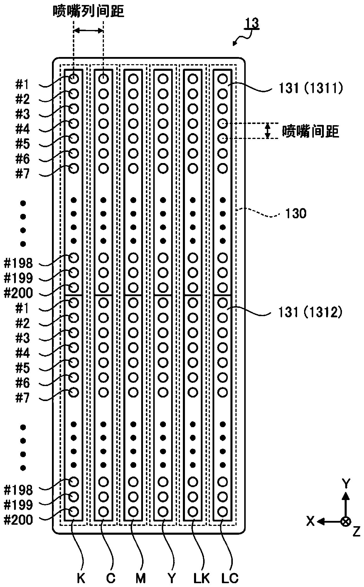
[0151] Figure 14 It is a schematic diagram showing a configuration example and cyclic operation of the recording head 13 that realizes recording in the recording method of the present embodiment by the full-color printer 100 .
[0152] In addition to the black ink nozzle row K, the five nozzle rows 130 (cyan ink nozzle row C, magenta ink nozzle row M, yellow ink nozzle row Y, gray ink nozzle row LK, light cyan ink nozzle row LC) The structure and recording method are the same as those in Example 1. Although the black ink nozzle row K has four nozzle tips 1...
PUM
 Abstract
Description
Claims
Application Information
 - R&D Engineer
- R&D Manager
- IP Professional
- Industry Leading Data Capabilities
- Powerful AI technology
- Patent DNA Extraction
Browse by: Latest US Patents, China's latest patents, Technical Efficacy Thesaurus, Application Domain, Technology Topic, Popular Technical Reports.
© 2024 PatSnap. All rights reserved.Legal|Privacy policy|Modern Slavery Act Transparency Statement|Sitemap|About US| Contact US: help@patsnap.com