Unmanned aerial vehicle with a buffering protection device through using a knee structure as basis to achieve pressure bending

A technology of protection device and buffer device, which is applied in the direction of wings, aircraft parts, aircraft control, etc., can solve the problems of reducing the effect of shock absorption, failure of buffering, broken brackets, etc., to achieve stable buffering work, uniform absorption, and good shock absorption Effect of shock absorbing work

Active Publication Date: 2020-02-11
安徽天鹰兄弟无人机科技创新有限公司
View PDF6 Cites 0 Cited by
  • Summary
  • Abstract
  • Description
  • Claims
  • Application Information

AI Technical Summary

Problems solved by technology

[0003] When performing landing buffering work, when the spring is used for shock absorption and buffering, a critical point of compression will occur when the spring is compressed, and at the same time, the effect of shock absorption will be reduced under the condition of continued compression, and it cannot be buffered. At the same time, through the internal The rigid bracket connects the equipment and the spring. After contacting the bottom surface, it is easy to cause the internal bracket to break due to force, so that the components of the drone are damaged and need to be replaced frequently, or even scrapped.

Method used


Image

  • Unmanned aerial vehicle with a buffering protection device through using a knee structure as basis to achieve pressure bending
  • Unmanned aerial vehicle with a buffering protection device through using a knee structure as basis to achieve pressure bending
  • Unmanned aerial vehicle with a buffering protection device through using a knee structure as basis to achieve pressure bending

Examples


Embodiment

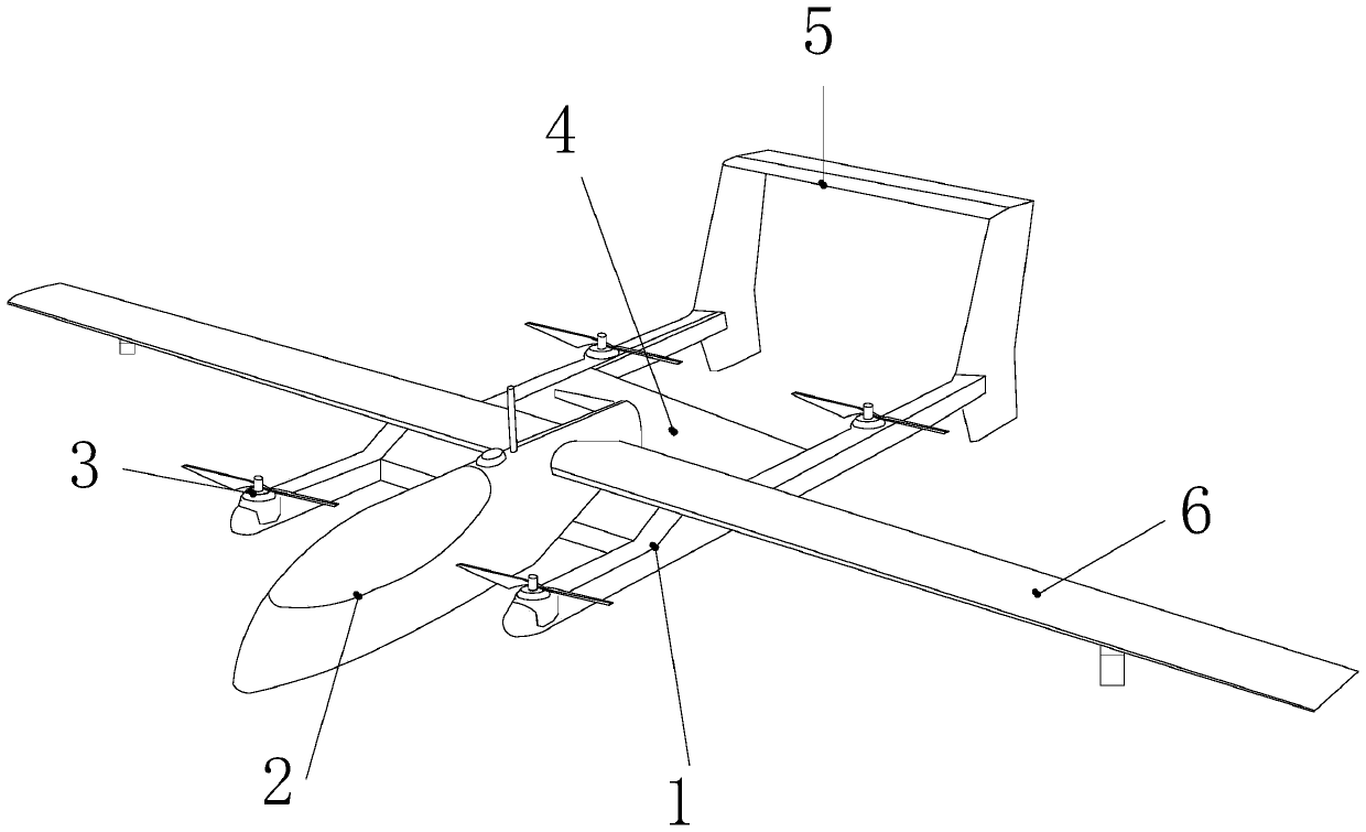
[0027] see figure 1 , the present invention provides an unmanned aerial vehicle with a buffer protection device that is bent under pressure based on the knee structure. The wing 6 is located on the left and right sides of the operation cabin 2 and is fixedly connected with the operation cabin 2. The intelligent buffer device 4 is provided with the lower end surface of the operation cabin 2 and is fixedly connected with the operation cabin 2 at the same time. The blade 3 is arranged on the support frame 1 The left and right sides of the upper end surface are fixedly connected, the support frame 1 is located at the lower end surface of the operation cabin 2 and is fixedly connected with the operation cabin 2, and the empennage 5 is located at the rear end surface of the support frame 1 and simultaneously connected with the support frame 1 is an integrated structure, and the empennage 5 is a gantry-type adjustable structure, and the movable structure of the gantry-type structure...


PUM


Abstract

The invention discloses an unmanned aerial vehicle with a buffering protection device through using a knee structure as a basis to achieve pressure bending. The unmanned aerial vehicle structurally comprises a supporting frame, an operating cabin, blades, an intelligent buffering device, an empennage, and wings. An internal stressed frame makes contact with a floor, power is received through a joint block at the same time, bending is carried out, an overall structure at the upper portion is pressed downwards at the same time, then a universal wheel at the upper portion is rotated, then a sliding frame is displaced and rotated, and a supporting pad is subjected to suction and separation, so that the device is prevented from quickly making contact with the damaged impression of a support; and then an internal pressing pad is pushed through a hinge rod at the upper part, so that internal gas is discharged, an internal air pressure pad is expanded at the same time, and then a memory spongeinside a damping pad is compressed, so that impulsive force is subjected to secondary pushing for damping, and the gas displacement replaces an internal spring to buffer the operation of the internaldevice.

Description

technical field [0001] The invention relates to the field of unmanned aerial vehicles, in particular to an unmanned aerial vehicle with a buffer protection device that is bent under compression based on a knee structure. Background technique [0002] When the current UAV is landing, the spring inside the internal rigid bracket is used to shock-absorb and buffer the device through the spring’s rebound and contraction after the device touches the ground when it lands, but in this way: [0003] When performing landing buffering work, when the spring is used for shock absorption and buffering, a critical point of compression will occur when the spring is compressed, and at the same time, the effect of shock absorption will be reduced under the condition of continued compression, and it cannot be buffered. At the same time, through the internal The rigid bracket is used to connect the equipment and the spring. After contacting the bottom surface, it is easy to cause the internal ...

Claims


Application Information

Patent Timeline
Patent Type & Authority Applications(China)
IPC IPC(8): B64C25/58B64C25/32B64C25/08B64C3/00B64C5/10
CPCB64C3/00B64C5/10B64C25/08B64C25/32B64C25/58
Inventor 徐勇
Owner 安徽天鹰兄弟无人机科技创新有限公司
Why Eureka
Try Eureka