
External wall assembling structure of fabricated building and construction method of external wall assembling structure

An assembly structure and assembly technology, applied in the direction of building components, building structure, construction, etc., can solve the problems affecting the installation and abutment of wall panels, and achieve the effect that the seismic performance is not easy

Inactive Publication Date: 2020-02-11
深圳市正知建筑技术有限公司
View PDF7 Cites 2 Cited by
  • Summary
  • Abstract
  • Description
  • Claims
  • Application Information

AI Technical Summary

Problems solved by technology

[0004] However, the beams are usually cast-in-place on the lower wall panels, and the overall volume of the beams will change during the solidification process. During installation, the lower end cannot be in contact with the upper end of the anti-sill and the upper end of the beam at the same time, thus affecting the installation of the wall panel

Method used


Image

  • External wall assembling structure of fabricated building and construction method of external wall assembling structure
  • External wall assembling structure of fabricated building and construction method of external wall assembling structure

Examples


Embodiment 1

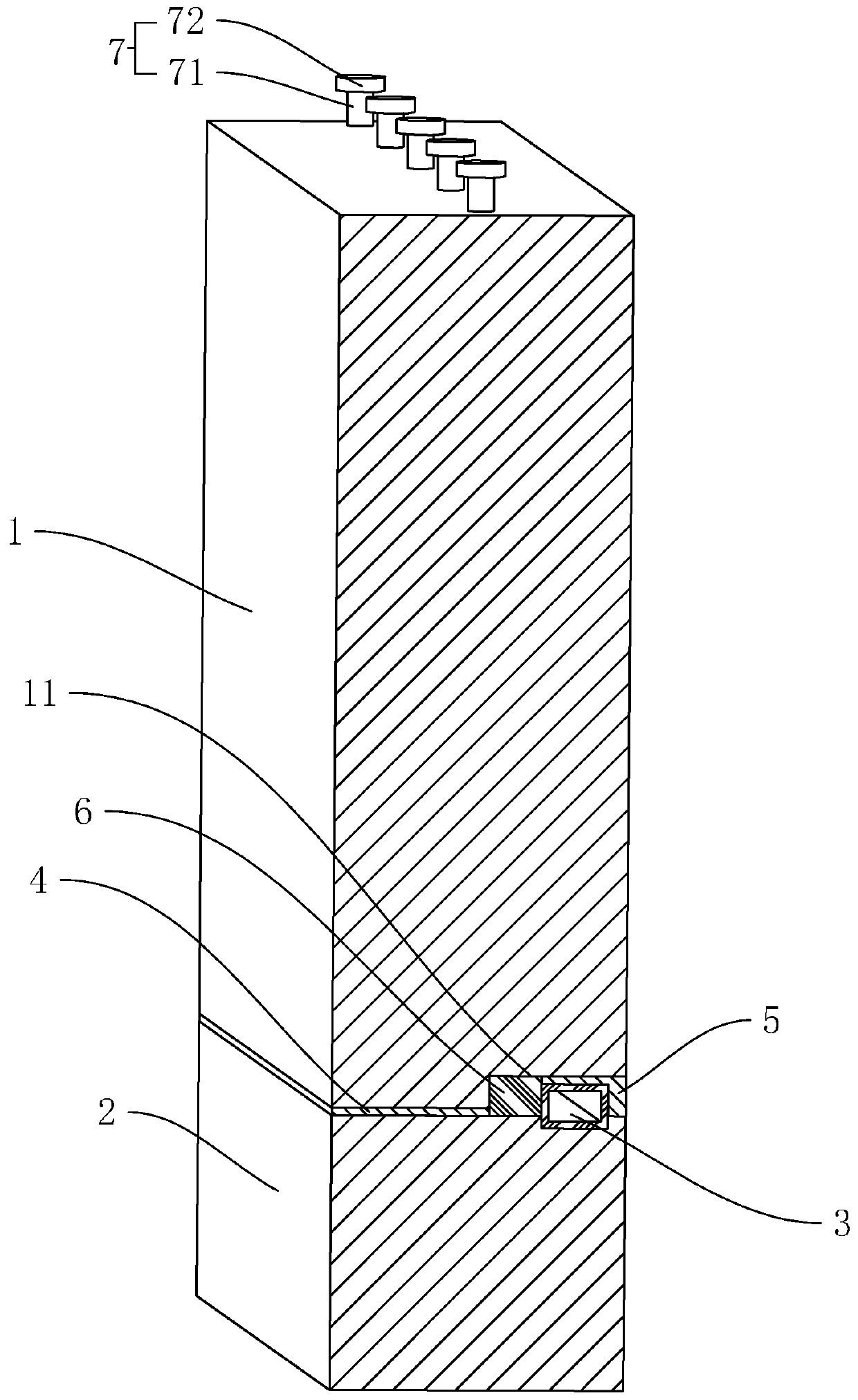
[0037] Embodiment 1: a kind of exterior wall assembly structure of prefabricated building, such as figure 1 As shown, it includes a number of vertically arranged wall panels 1, and beams 2 are arranged between the upper and lower adjacent wall panels 1. Plate 1 cast-in-place connection. The upper end of the beam 2 is provided with a square channel 3, which is a galvanized steel square tube, which abuts against the upper end of the unsolidified beam 2, and the two are fixed, and the square channel 3 is located at a position where the beam 2 is far away from the outer wall of the wallboard 1. The lower end of the wall panel 1 is provided with a waterproof groove 11, and the waterproof groove 11 penetrates the inner wall of the wall panel 1. When the lower end of the wall panel 1 above is in contact with the upper end of the beam 2, the top surface of the waterproof groove 11 is in contact with the upper surface of the square channel 3. . After the beam 2 is solidified, place t...

Embodiment 2

[0044] Embodiment 2: a kind of exterior wall construction method of prefabricated building, comprises the following steps:

[0045] S1, fixing a wall panel 1 to the foundation or the lower beam 2;

[0046] S2. Set up a formwork on the upper end of the installed wall panel 1, use concrete to pour the beam 2 in the plank, so that the beam 2 is connected with the load-bearing column;

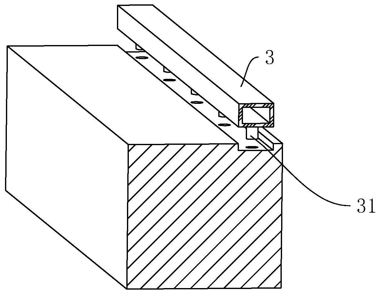
[0047] S3. Place the square tube 3 on the upper end of the beam 2 that has not exceeded the initial setting time, insert the connecting column 31 of the square tube 3 into the beam 2, and make the lower end of the square tube 3 and the upper end of the beam 2 be on the same plane;

[0048] S4. Place the elastic member 6 on the upper end of the beam 2, make the elastic member 6 abut against the side wall of the square channel 3 facing the outer wall of the wall panel 1, place another wall panel 1 on the upper end of the completely solidified beam 2, and make the wall The lower end surface of the bo...


PUM


Abstract

The invention discloses a composite prefabricated external wall structure of a fabricated building and a construction method of the composite prefabricated external wall structure and belongs to the field of fabricated buildings. According to the technical scheme, the composite prefabricated external wall structure is characterized by comprising a plurality of wallboards arranged in the vertical direction; a cross beam is arranged between every two adjacent wallboards; a waterproof tank is arranged at the lower end of each wallboard; the waterproof tank penetrates through the inner lateral side of each wallboard; the upper end of each cross beam is provided with a square section, the upper end of each square section abuts against the top face of the corresponding waterproof tank of the corresponding upper wallboard; and the upper ends of the cross beams abut against the lower ends of the upper wallboards. According to the composite prefabricated external wall structure, the structure is reasonable, the square sections are arranged at the upper ends of the cross beams not initially set, then the distance between the upper end faces of the square sections and the upper end faces of the cross beams is determined, the lower end faces of the wallboards can abut against the upper ends of the cross beams when the wallboards are mounted; and the top faces of the waterproof tanks can abut against the upper end faces of the square sections, and then the wallboards are not likely to generating skewing, so that the wallboards are more stable in the use process.

Description

technical field [0001] The invention belongs to a prefabricated building, more specifically, it relates to an exterior wall assembly structure of a prefabricated building and a construction method thereof. Background technique [0002] Prefabricated concrete structure refers to the standardized production of various components of the structure, including prefabricated shear walls, prefabricated beams, prefabricated columns, prefabricated floors, prefabricated wall panels, etc., and then the prefabricated components are bolted and welded at the construction site. A structure formed by connection or cast-in-place connection installation. The industrial production of each prefabricated component of the prefabricated concrete structure has the advantages of saving labor force, fast construction progress, helping to realize building energy conservation, facilitating industrial production and mechanized construction, etc., and adapting to the development direction of my country's ...

Claims


Application Information

Patent Timeline
IPC IPC(8): E04B2/64E04B1/70
CPCE04B1/7046E04B2/64
Inventor 魏泽科
Owner 深圳市正知建筑技术有限公司
Learn More