Piston type pneumatic control valve

An air-controlled valve and piston-type technology, applied in valve details, multi-way valves, valve devices, etc., can solve problems such as cumulative errors, affecting transmission efficiency, and internal parts stuck, achieving small deviations, good sealing effects, and easy assembly The effect of small deviation

Inactive Publication Date: 2018-08-14
CRRC QINGDAO SIFANG ROLLING STOCK RES INST
View PDF6 Cites 1 Cited by
  • Summary
  • Abstract
  • Description
  • Claims
  • Application Information

AI Technical Summary

Problems solved by technology

[0003] see figure 1 As shown, the existing piston air control valve 200 is generally sealed by vulcanized rubber components, the structure of the motion unit is complex, and the assembly is cumbersome
The vulcanized valve core 202 is set on the piston-type valve stem 201, and is fixed by the retaining ring 204 for the shaft. The piston rod 201 is guided by the guide valve seat 203, and the guide valve seat 203 is pressed into the piston-type air control valve 200 through the end cover 205. , the piston-type air control valve 200 is a single-guided valve (that is, the upper end is guided), the valve stem 201 is prone to deflection, and the piston-type air control valve 200 is prone to cumulative errors, which in turn affects the transmission efficiency, and it has a great influence on the machining accuracy and assembly High precision requirements, the above shortcomings lead to high production costs of the valve itself, and the internal components are prone to jamming and wear when they move relatively, which in turn increases the probability of component failure, resulting in a substantial increase in use and maintenance costs

Method used


Image

  • Piston type pneumatic control valve
  • Piston type pneumatic control valve
  • Piston type pneumatic control valve

Examples


Embodiment Construction

[0019] In order to make the purpose, technical solution and advantages of the present invention clearer, the embodiments of the present invention will be further described in detail below in conjunction with the accompanying drawings.

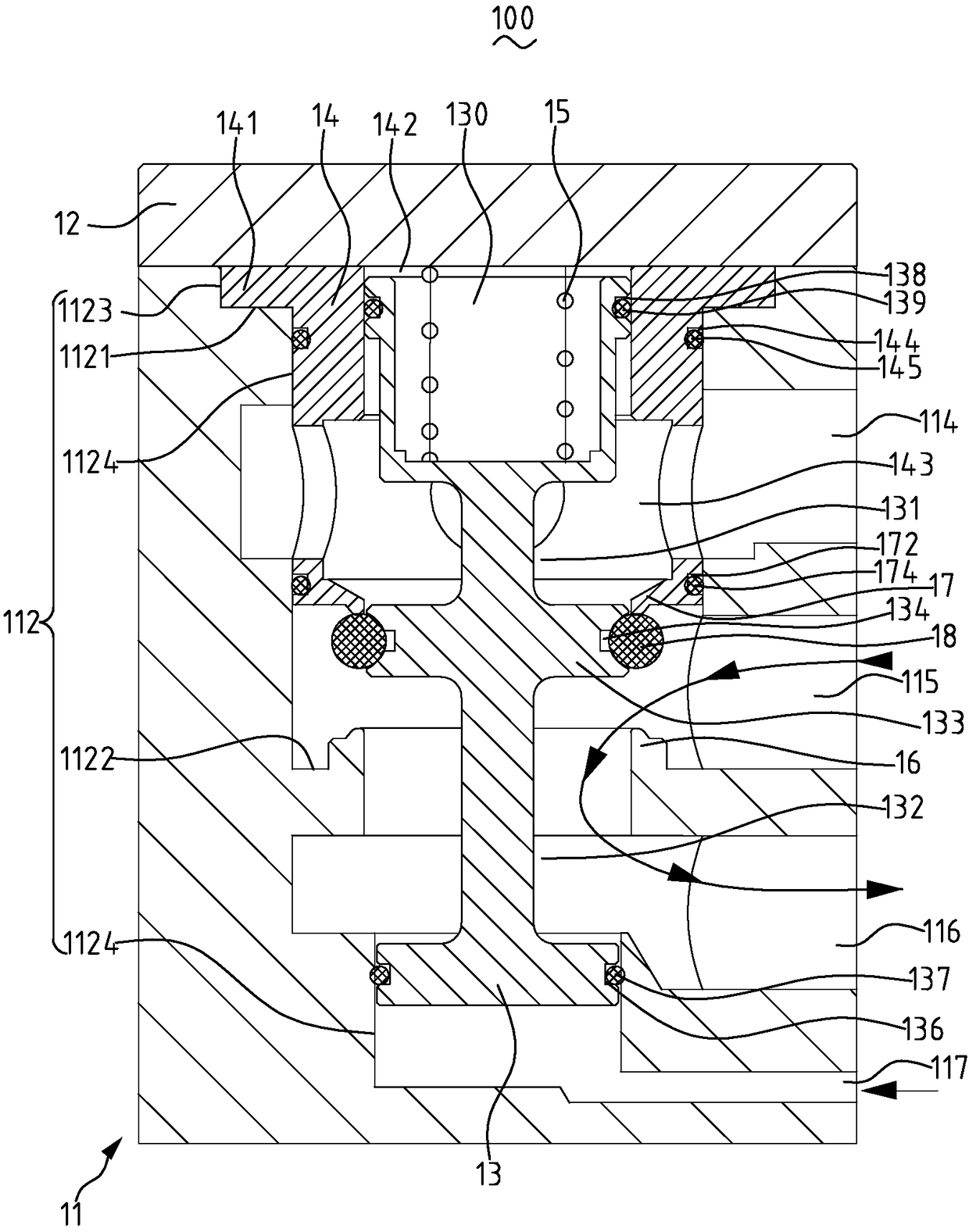
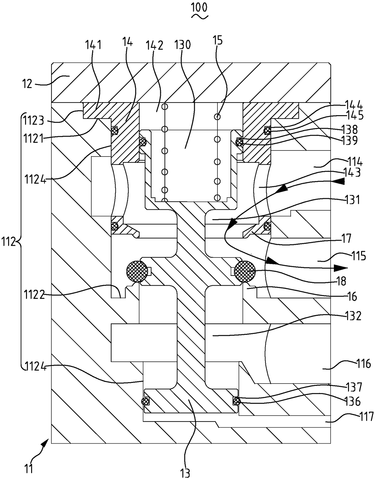
[0020] figure 2 It is a schematic diagram of the structure of the piston air control valve of the present invention in the normal ventilation position, image 3 It is a structural schematic diagram of the piston air control valve of the present invention in the forced release position. Specifically, see Figure 2 to Figure 3 , The piston-type air-operated valve 100 of the present invention includes a valve body 11 , a valve cover 12 , a valve stem 13 , a guide valve seat 14 , a spring 15 , a lower valve port 16 , an upper valve port 17 , and a sealing ring valve core 18 . The piston air control valve 100 changes the pressure change at the lower end of the valve rod 13 through the control port 117 to switch on and off the compressed air to re...


PUM


Abstract

The invention relates to a piston type pneumatic control valve which comprises a valve body, a valve cover, a valve rod, a guiding valve seat, a spring, a lower valve port, an upper valve port and a seal ring type valve element. A stepped blind hole is formed in the upper end of the valve body; an air inlet, an air outlet, an air discharge hole and a control port communicating with the stepped blind hole are sequentially formed in the side surface of the valve body from top to bottom; the lower part of the valve rod is inserted into the lower part of the stepped blind hole and can axially movealong the blind hole; the lower end of the valve rod is higher than the control port; the upper part of the valve rod is inserted into an axial through hole of the guiding valve seat and can axiallymove along the through hole; the guiding valve seat is inserted and clamped to the upper part of the stepped blind hole; the upper valve port is formed in the lower end of the guiding valve seat; thelower valve port is formed in the stepped blind hole under the upper valve port; the seal ring type valve element is sleeved in the middle of the valve rod and is located between the lower valve portand the upper valve port; the valve cover is detachably fastened onto the stepped blind hole; and the spring is clamped between the valve cover and the valve rod.

Description

technical field [0001] The invention relates to the technical field of a valve body, in particular to a piston type air control valve. Background technique [0002] The braking (also known as braking) may not be relieved during the operation of rail vehicles. In order to ensure that the vehicle can move to the depot when the brakes are not relieved, the brake control device and the output port of the parking control module are generally A piston-type air control valve is installed at the center, and the air passage of the piston-type air-control valve is controlled by a solenoid valve to realize remote automatic braking isolation. The setting of this valve also provides the basis for automatic driving. [0003] see figure 1 As shown, the existing piston-type air control valve 200 is generally sealed by a vulcanized rubber component, and the structure of the motion unit is complicated and the assembly is cumbersome. The vulcanized valve core 202 is set on the piston-type va...

Claims


Application Information

Patent Timeline
Patent Type & Authority Applications(China)
IPC IPC(8): F16K11/044F16K31/122
CPCF16K11/044F16K31/1221
Inventor 张振超
Owner CRRC QINGDAO SIFANG ROLLING STOCK RES INST
Why Eureka
Try Eureka