
A kind of glass curtain wall structure and its construction method

A glass curtain wall and panel technology, applied in the direction of walls, building components, building structures, etc., can solve the problems of troublesome separation of panels and suction cups, high adsorption strength, low construction efficiency, etc., to achieve efficient assembly and disassembly operations, safe disassembly process, The effect of easy assembly and disassembly

Active Publication Date: 2020-08-14
台州宝盾科技有限公司
View PDF1 Cites 0 Cited by
  • Summary
  • Abstract
  • Description
  • Claims
  • Application Information

AI Technical Summary

Problems solved by technology

[0004] 1. When disassembling the panel of this structure, complex special disassembly tools are required, and common tools cannot be used for disassembly and construction, which is very troublesome
[0005] 2. The special disassembly tool uses a suction cup to fix the panel. In order to avoid the panel from falling off during the disassembly process, the suction cup has high adsorption strength to the panel, which makes it troublesome to separate the panel from the suction cup after disassembly, so the construction efficiency is low.
[0006] 3. During the whole process of installation and disassembly, only the suction cup is used to absorb and fix the panel, which has great potential safety hazards

Method used


Image

  • A kind of glass curtain wall structure and its construction method
  • A kind of glass curtain wall structure and its construction method
  • A kind of glass curtain wall structure and its construction method

Examples


Embodiment Construction

[0052] The following are specific embodiments of the present invention and in conjunction with the accompanying drawings, the technical solutions of the present invention are further described, but the present invention is not limited to these embodiments.

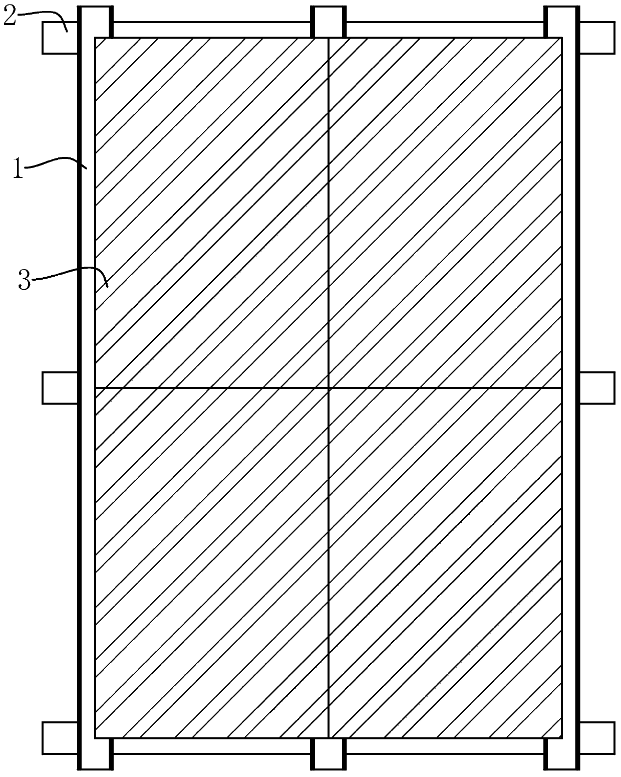
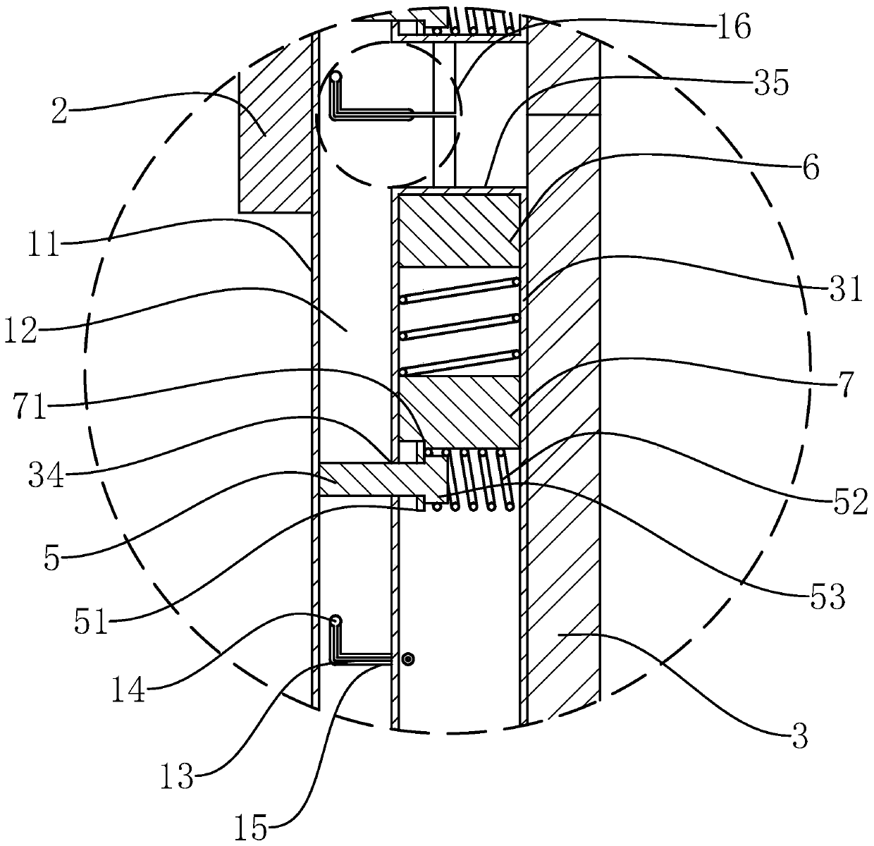
[0053] Such as Figure 1-12 As shown, a glass curtain wall structure of the present invention includes a keel and a panel 3, the keel includes a number of vertical columns 1, the panel 3 is made of tempered glass material, and is a rectangular plate structure, and the inner surface of the panel 3 is close to the left and right sides A connecting pipe 31 is fixed at each position, and the connecting pipe 31 is a rectangular pipe structure arranged vertically, and the connecting pipe 31 is formed by enclosing the front pipe wall and the rear pipe wall parallel to each other, and the outer pipe wall and the inner pipe wall parallel to each other. , the front wall of the connecting pipe 31 is fixed to the inner surface of the ...


PUM


Abstract

The invention provides a glass curtain wall structure and a construction method thereof, belongs to the field of building curtain walls, and solves the problem that the construction efficiency of an existing glass curtain wall is low. The glass curtain wall structure comprises a channel steel structure stand column and a panel, wherein a connecting pipe is fixed on the inner side surface of the panel, and a connecting mechanism and a pushing mechanism are arranged on the connecting pipe; the connecting mechanism comprises a rod hole located on the inner pipe wall of the connecting pipe, a connecting rod penetrates through the rod hole, a clamping block is fixed to the outer end of the connecting rod, an embedding groove is formed in the hole wall at the outer end of the rod hole, and a reset block is fixed on the connecting rod, and a reset spring sleeves the connecting rod; the pushing mechanism comprises a pushing hole located in the rear pipe wall of the connecting pipe, wherein a push rod is penetrates through the pushing hole, a push plate is fixed to the front end of the push rod, a compression spring is arranged in the connecting pipe, and the pushing mechanism further comprises an alignment block fixed in the connecting pipe and a stop block located in the connecting pipe, wherein a stop groove is formed below the stop block; and an L-shaped connecting hole is formed ina side plate, a clamping hole is formed in the top end of the rear section of the connecting hole, and a clamping groove is formed in the inner side surface of the side plate . The curtain wall structure construction process is safe, efficient and convenient.

Description

technical field [0001] The invention belongs to the technical field of building curtain walls, and relates to a glass curtain wall structure and a construction method thereof. Background technique [0002] The glass curtain wall refers to the building envelope or decorative structure formed by the connection of the supporting structure and the panel. The glass curtain wall is a beautiful and novel method of building wall decoration. According to whether the supporting structure is visible, glass curtain walls are generally divided into open frame and hidden frame structures. [0003] For example, the Chinese invention patent application titled "A Hidden Frame Glass Curtain Wall and Special Disassembly Tool and Installation Method" with application number 201810034659.7 includes a frame and panels fixed on the frame through a connecting mechanism. Hidden to form a hidden frame curtain wall structure, but it has the following problems: [0004] 1. When disassembling the pane...

Claims


Application Information

Patent Timeline
Patent Type & Authority Patents(China)
IPC IPC(8): E04B2/96E04B1/343
CPCE04B1/34321E04B2/96
Inventor 林玉平
Owner 台州宝盾科技有限公司
Learn More