Display panel and display device
A technology of display panel and display area, applied in the direction of diodes, semiconductor devices, electrical components, etc., can solve the problem of intrusion into the evaporation film layer, etc., and achieve the effect of improving reliability
Active Publication Date: 2020-02-11
WUHAN TIANMA MICRO ELECTRONICS CO LTD
4 Cites 4 Cited by
AI-Extracted Technical Summary
Problems solved by technology
[0003] The present invention provides a display panel and a display device. The above-mentioned display panel is used to solve the problem that water vapor i...
Method used
In the above-mentioned partition structure, in order to better prevent water vapor from spreading along the direction parallel to the boundary of the through hole, avoid that the evaporated film layer 4 is connected along the sidewall of the radial partition groove 22 to form an uninterrupted point, radial partition The cross-sectional shape of the groove can also be set as an inverted T shape. As shown in FIG. 8 , the inverted T-shaped radial partition groove 22 can reduce the generation of uninterrupted points of the evaporated film layer 4 in the radial partition groove 22 .
Optionally, as shown in Figure 7a and Figure 7b, it is a schematic structural view of the partition structure provided by the embodiment of the present invention, there are multiple uniformly distributed diameters between any adjacent two annular partition grooves 21 To the partition groove 22. A plurality of radial partition grooves 22 are evenly distributed between two adjacent annular partition grooves 21 , which can reduce the probability of water vapor entering the oxidation evaporation film layer through unblocked points on the two annular partition grooves. Of course, the plurality of radial partition grooves may also be unevenly distributed between two adjacent partition grooves, which may be determined according to actual conditions.
Specifically, for the above-mentioned partition structure, as shown in Figures 7a and 7b, the radial partition groove 22 and its adjacent two annular partition grooves 21 can all communicate, and the annular partition groove and the radial partition recess The intersection of the grooves can also isolate the evaporated film layer, increasing the probability of blocking water vapor intrusion. It is also possible that the radial partition groove is not connected to the two adjacent annular partition grooves, or a part of the plurality of radial partition grooves i...
Abstract
The invention relates to the technical field of display, and discloses a display panel and a display device. The display panel comprises a substrate, an evaporation film layer arranged on one side ofthe substrate and a packaging layer arranged on the side of the evaporation film layer deviating from the substrate. The display panel comprises a display area and a first non-display area. The display area at least semi-surrounds the first non-display area. The first non-display area comprises a through hole and a partition structure positioned between the through hole and the display area. The partition structure is arranged between the surface of the side of the substrate away from the evaporation film layer and the evaporation film layer. The partition structure includes a plurality of annular partition grooves surrounding the through hole and at least one radial partition groove extending toward the through hole between at least two adjacent annular partition grooves. The groove portsof the annular partition grooves and the radial partition grooves facing the evaporation film layer. The radial partition grooves between the two adjacent annular partition grooves in the display panel can prevent water vapor from invading the evaporation film layer layer by layer in the direction parallel to the through hole boundary so as to improve the reliability of the display panel.
Application Domain
Solid-state devicesSemiconductor devices
Technology Topic
PhysicsComposite material +3
Image
Examples
- Experimental program(1)
Example Embodiment
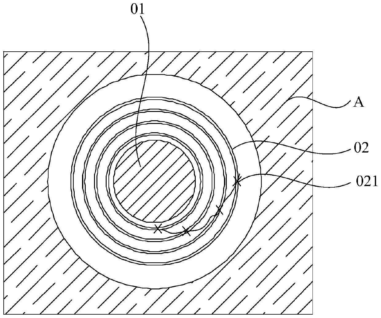
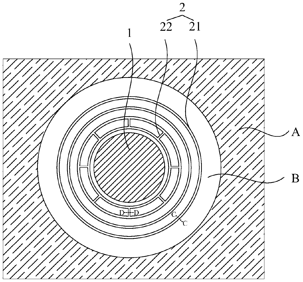
[0030] Currently, such as figure 1 As shown, for a display panel with a hole 01 in the display area A, the hole-digging process on the display panel will directly expose the vapor-deposited film on the entire surface, and external water vapor will enter through the hole and oxidize the vapor-deposited film. To prevent water vapor from entering, usually multiple ring-shaped trenches 02 are set around the external control, which can directly isolate the vapor deposition film naturally during the vapor deposition process to prevent water vapor from intruding. But like figure 1 As shown, when the vapor deposition film layer is not completely blocked at a certain part of an annular groove, water vapor will invade the oxidation vapor deposition film along the uninterrupted point 021. When there are uninterrupted at different positions of multiple annular grooves at the same time When it is clicked, water vapor will invade layer by layer along the direction parallel to the boundary of the hole, which will eventually lead to the failure of the display panel packaging.
[0031] In view of the problem that the display panel in the related art encounters water vapor intrusion, embodiments of the present invention provide a display panel and a display device. In order to make the objectives, technical solutions and advantages of the present invention clearer, the specific implementations of the display panel and the display device provided by the embodiments of the present invention will be described in detail below with reference to the accompanying drawings. It should be understood that the preferred embodiments described below are only used to illustrate and explain the present invention, but not to limit the present invention. And if there is no conflict, the embodiments in the application and the features in the embodiments can be combined with each other.
[0032] The shapes and sizes of the components in the drawings do not reflect the true proportions, and are only intended to illustrate the content of the present invention.
[0033] The embodiment of the present invention provides a display panel, such as figure 2 As shown, figure 2 It is a schematic structural diagram of a display panel provided by an embodiment of the present invention, including a display area A and a first non-display area B. The display area A at least half surrounds the first non-display area B, and the first non-display area B includes a through hole 1 And a partition structure 2 located between the through hole 1 and the display area A;
[0034] Specifically, such as image 3 As shown, image 3 for figure 2 A cross-sectional view along the cutting line CC or a cross-sectional view along the cutting line DD, the display panel includes a substrate 3, an evaporated film layer 4 on the side of the substrate 3, and an encapsulation layer 6 on the side of the evaporated film 4 away from the substrate 3;
[0035] The partition structure 2 is located between the surface of the substrate 3 on the side away from the vapor deposition film layer 4 and the vapor deposition film layer 4, and the partition structure 2 includes, for example, figure 2 with image 3 Shown:
[0036] A plurality of annular partition grooves 21 surrounding the through hole 1 and at least one of the radial partition grooves 22 existing at least between two adjacent annular partition grooves 21 facing toward the through hole 1, wherein the annular partition groove The groove 21 and the notch of the radial partition groove 22 face the evaporated film layer 4.
[0037] The display panel provided by the foregoing invention embodiments includes a display area A and a first non-display area B. The display area A at least half surrounds the first non-display area B. The first non-display area B includes a through hole 1 and a first non-display area B. The partition structure 2 between the display area A and the display area A includes a plurality of annular partition grooves 21 surrounding the through hole 1 and at least one extending direction existing between two adjacent annular partition grooves 21 facing the communication channel. When the radial partition groove 22 of the hole 1 is vapor-deposited on the side of the annular partition groove 21 and the notch side of the radial partition groove 22 to form the vapor deposition film layer 4, such as image 3 As shown, the annular partition groove 21 can isolate the vapor-deposited film layer 4 in the first non-display area B, and prevent water vapor from invading the oxidized vapor-deposited film layer 4 inside the display panel from the through hole 1, and two adjacent annular partition grooves At least one radial partition groove 22 between 21 can block the vapor-deposited film layer 4 along the direction parallel to the boundary of the through hole 1, thereby preventing the spread of water vapor along the direction parallel to the boundary of the through hole, that is, reducing the amount of water vapor passing through. The probability that the uninterrupted point on the ring-shaped partition groove 21 enters the oxidized vapor-deposited film layer 4 inside the display panel further improves the reliability of the display panel.
[0038] Specifically, the through hole on the first non-display area is used to install a camera, such as Figure 4a As shown, the display area A may half-enclose the first non-display area B, and the through hole 1 is located at an edge of the display area A; or, as Figure 4b As shown, the display can completely surround the first non-display area B, and the through hole 1 for installing the camera is located in the display area A. Such as figure 2 As shown, a partition structure 2 is provided between the through hole 1 and the display area A, which can prevent water vapor from entering from the through hole to oxidize the evaporated film layer. It should be noted that the display panel may also include a second non-display area, wherein the second non-display area is arranged around the display area A. Optionally, the second non-display area is used to provide peripheral circuits including a gate driving circuit and a light emitting control circuit.
[0039] It should be noted that the above structure is suitable for organic electroluminescence (OLED) display panels, such as Figure 5 As shown, Figure 5 It is a schematic structural diagram of an organic electroluminescence display panel. The organic electroluminescence display panel may include a substrate 3, an anode layer 51 formed on the side of the substrate 3, and a light-emitting layer formed on the side of the anode layer 51 away from the substrate 3 52 and the cathode layer 53 formed on the side of the light-emitting layer 52 away from the anode layer 51 and the encapsulation layer 6 on the side of the cathode layer 53 away from the light-emitting layer 52. The anode layer 51 needs to be patterned during production, and it is not required The luminescent layer 52 and the cathode layer 53 do not need to be patterned and need to be fully evaporated. The evaporated film layer 4 can be one or more of the luminescent layer 52 and the cathode layer 53, wherein, The light emitting layer 52 may include one or more of a hole injection layer, a hole transport layer, a light emitting layer, an electron transport layer, and an electron injection layer. Specifically, the specific structure of the organic electroluminescence display panel may also include a substrate, an anode, a hole injection layer, a hole transport layer, a light emitting layer, an electron transport layer, an electron injection layer, and a cathode layer arranged in sequence. The anode layer requires Patterning treatment does not require full evaporation, and the hole injection layer, hole transport layer, light-emitting layer, electron transport layer, electron injection layer, and cathode layer can be fully evaporated evaporation film layers. The specific structure of the above-mentioned organic electroluminescent display panel can be determined according to actual conditions without any specific limitation, and the vapor-deposited film layer to be fully vaporized can also be determined according to actual conditions.
[0040] Specifically, the aforementioned partition structure is located between the surface of the substrate 3 on the side away from the vapor-deposited film layer 4 and the vapor-deposited film layer 4. Optionally, such as Figure 6a As shown, Figure 6a It is a schematic diagram of the structure of a base provided by an embodiment of the present invention. The base 3 may include a first flexible substrate 31 and a first buffer layer 32 stacked in sequence. The first buffer layer 32 is located on the first flexible substrate 31 and the evaporated film layer 4 In between, the partition structure 2 may be provided on the first buffer layer 32 and the first flexible substrate 31. When the vapor deposition film layer is formed, the partition structure partitions the vapor deposition film layer near the through hole. Optionally, in order to increase the flexibility of the base and facilitate the formation of a partition structure on the base, the base may also include a combination of multiple flexible substrates and buffer layers arranged alternately, for example, Figure 6b As shown, Figure 6b It is a schematic diagram of the structure of a base provided by an embodiment of the present invention. The base includes a second flexible substrate 33, a second buffer layer 34, a first flexible substrate 31, and a first buffer layer 32 stacked in sequence, and the first buffer layer 32 is located Between the first flexible substrate 31 and the vapor-deposited film layer 4, the partition structure 2 may be provided on the first buffer layer 32 and the first flexible substrate 31. When the vapor-deposited film layer is formed, the partition structure cuts off the vapor-deposited film layer near the through hole. In the display panel, the film layer between the surface of the substrate away from the vapor-deposited film layer and the vapor-deposited film layer can be set according to specific conditions, and is not specifically limited here. The film layer where the partition structure is located can also be determined according to actual conditions.
[0041] In the display panel provided by the foregoing invention embodiments, for the arrangement of the partition structure, a plurality of annular partition grooves may be evenly spaced around the through holes, or may be unevenly arranged, depending on actual conditions. Generally, the number of annular partition grooves can be set to 4 to 6, depending on the actual situation, and there is no restriction here.
[0042] Specifically, in order to better prevent the spread of water vapor in the direction parallel to the boundary of the through hole, and reduce the probability that water vapor enters the oxidation vapor deposition film layer inside the display panel through the uninterrupted points on the multiple annular partition grooves, it can be in any adjacent At least one radial partition groove is arranged between the two annular partition grooves.
[0043] Specifically, a plurality of radial partition grooves may be arranged between any two adjacent annular partition grooves.
[0044] Optionally, such as Figure 7a with Figure 7b As shown, it is a schematic structural diagram of a partition structure provided by an embodiment of the present invention. Any two adjacent annular partition grooves 21 have a plurality of evenly distributed radial partition grooves 22 between them. A plurality of radial partition grooves 22 are evenly distributed between two adjacent annular partition grooves 21, which can reduce the probability that water vapor enters the oxidation vapor deposition film through uninterrupted points on the two annular partition grooves. Of course, a plurality of radial partition grooves may also be unevenly distributed between two adjacent partition grooves, which may be determined according to actual conditions.
[0045] Specifically, in the case that there are a plurality of evenly distributed radial partition grooves 22 between two annular partition grooves 21, the radial partition groove 22 between two adjacent annular partition grooves 21 forms a diameter. The radial partition grooves 22 in the two adjacent radial partition groove groups can be aligned one by one. The radial partition grooves and the annular partition grooves form a network-shaped partition structure. Separate the vapor deposition film layer as much as possible, increase the path to prevent water vapor from invading the vapor deposition film layer, and improve the reliability of the display panel. Such as Figure 7a As shown, each radial partition groove group includes a plurality of radial partition grooves 22, the plurality of radial partition grooves 22 are evenly distributed, and the radial partition grooves 22 in two adjacent radial partition groove groups are Align the settings one by one. Wherein, the number of radial partition grooves 22 in each radial partition groove group can be determined according to actual conditions and is not limited here. E.g, Figure 7a Here, each radial partition groove group can be specifically provided with 8 radial partition grooves 22, and the interval angle α between every two adjacent radial partition grooves 22 is 45°.
[0046] Specifically, in the case that there are a plurality of evenly distributed radial partition grooves 22 between two annular partition grooves 21, the radial partition groove 22 between two adjacent annular partition grooves 21 forms a diameter. The radial partition grooves 22 in the two adjacent radial partition groove groups can be arranged in a staggered manner, which can isolate the vapor deposition film layer near the through hole as much as possible, and increase the path for preventing water vapor intrusion. , Improve the reliability of the display panel. Such as Figure 7b As shown, each radial partition groove group includes a plurality of radial partition grooves 22, the plurality of radial partition grooves 22 are evenly distributed, and the radial partition grooves 22 in two adjacent radial partition groove groups are Staggered settings. Among them, the number of radial partition grooves 22 in each radial partition groove group and the staggered spacing angle of the radial partition grooves 22 in two adjacent radial partition groove groups can be determined according to actual conditions. There are no restrictions here. E.g, Figure 7b Each radial partition groove group can be specifically provided with 4 radial partition grooves 22, and the interval angle between two adjacent radial partition grooves 22 in a radial partition groove group is 90°. The radial partition grooves 22 in the two radial partition groove groups are alternately arranged at an interval angle β of 45°.
[0047] Specifically, for the above partition structure, such as Figure 7a with 7b As shown, the radial partition groove 22 and the two adjacent annular partition grooves 21 can be both connected, and the evaporation film layer can also be blocked at the intersection of the annular partition groove and the radial partition groove, thereby increasing the resistance to water vapor intrusion The odds. It is also possible that the radial partition groove is not in communication with the two adjacent annular partition grooves, or a part of the multiple radial partition grooves in the radial partition groove group is connected with the two adjacent annular partition grooves, The other part is not connected with the two adjacent annular partition grooves, and can also isolate the evaporated film layer between the annular partition grooves, and can prevent the spread of water vapor along the direction parallel to the boundary of the through hole. According to the actual situation, there is no restriction here.
[0048] In the above partition structure, optionally, multiple pairs of radial partition grooves 22 may be provided between two adjacent annular partition grooves 21, such as Figure 7c As shown, Figure 7c It is a schematic structural diagram of a partition structure provided by an embodiment of the present invention. Each pair of radial partition grooves 22 may include a first radial partition groove 221 and a second radial partition groove 222, wherein the first radial partition groove 221 and the second radial partition groove 222 are respectively connected to different annular partition grooves 21, and are arranged adjacent to each other in parallel. The radial partition grooves are formed in pairs between the annular partition grooves, and the pair of radial partition grooves The groove increases the probability of separating the vapor-deposited film between the annular partition grooves, and better prevents the spread of water vapor along the direction parallel to the boundary of the through hole. The number of pairs of radial partition grooves 22 provided between two adjacent annular partition grooves 21 can be determined according to actual conditions. Specifically, the multiple pairs of radial partition grooves 22 provided between two adjacent annular partition grooves 21 may be evenly distributed, and each pair of radial partition grooves between two different annular partition grooves 21 may be Staggered settings.
[0049] In the above partition structure, in order to better isolate the vapor-deposited film layer 4 and prevent the vapor-deposited film layer 4 from being connected along the sidewall of the annular partition groove 21 to form an uninterrupted point, the cross-sectional shape of the annular partition groove 21 can be set to an inverted T Font, such as Figure 8 As shown, Figure 8 This is a cross-sectional view of a partition structure provided by an embodiment of the present invention. When the vapor deposition film layer 4 is formed by vapor deposition, the inverted T-shaped annular partition groove 21 can reduce the vapor deposition film layer 4 in the annular partition groove 21 that is not partitioned. The production.
[0050] In the above-mentioned partition structure, in order to better prevent water vapor from spreading in the direction parallel to the boundary of the through hole, avoid the vapor deposition film layer 4 from being connected along the side wall of the radial partition groove 22 to form an uninterrupted point, which radially partitions the groove The cross-sectional shape can also be set to an inverted T shape, such as Figure 8 As shown, the inverted T-shaped radial partition groove 22 can reduce the occurrence of uninterrupted points of the evaporated film layer 4 in the radial partition groove 22.
[0051] Specifically, such as Figure 9a As shown, Figure 9a This is a cross-sectional view of a partition structure provided by an embodiment of the present invention. When the base 3 includes the first flexible substrate 31 and the first buffer layer 32, it can be set as the width of the portion where the annular partition groove 21 is located in the first buffer layer 32. d 1 Smaller than the width d of the portion of the annular partition groove 21 located on the first flexible substrate 31 2 , To reduce the generation of uninterrupted points of the vapor-deposited film layer 4. Optionally, such as Figure 9b As shown, when the substrate includes the second flexible substrate 33, the second buffer layer 34, the first flexible substrate 31, and the first buffer layer 32 which are stacked in sequence, the ring-shaped partition groove 21 can be arranged in the first buffer layer 32. The width of the part d 3 Smaller than the width d of the portion of the annular partition groove 21 located on the first flexible substrate 31 4 , To reduce the generation of uninterrupted points of the vapor-deposited film layer 4.
[0052] Specifically, such as Figure 9a As shown, Figure 9b This is a cross-sectional view of a partition structure provided by an embodiment of the present invention. When the base 3 includes the first flexible substrate 31 and the first buffer layer 32, it can be arranged such that the radial partition groove 22 is located in the portion of the first buffer layer 32. Width d 5 Smaller than the width d of the portion of the annular partition groove 21 located on the first flexible substrate 31 6 , To reduce the generation of uninterrupted points of the vapor-deposited film layer 4. Optionally, such as Figure 9b As shown, when the substrate includes a second flexible substrate 33, a second buffer layer 34, a first flexible substrate 31, and a first buffer layer 32 stacked in sequence, it can be arranged that the radial partition groove 22 is located in the first buffer layer 32. The width of the part d 7 Smaller than the width d of the portion of the radial partition groove 21 located on the first flexible substrate 31 8 , To reduce the generation of uninterrupted points of the vapor-deposited film layer 4.
[0053] The above-mentioned display panel also includes an encapsulation layer 6 on the side of the vapor-deposited film layer 4 facing away from the substrate 3 to prevent external moisture from invading the display panel. The above-mentioned encapsulation layer may include a multilayer inorganic encapsulation layer and an organic encapsulation layer arranged in a cross stack. The inorganic encapsulation layer 6 directly in contact with the evaporated film layer 4 is formed on the inorganic encapsulation layer 6 directly in contact with the evaporated film layer 4. There is a sealing part covering the inside of the annular partition groove 21 and the radial partition groove 22 for sealing the partition structure 2. For example, such as Picture 10 As shown, Picture 10 A cross-sectional view of a display panel provided by an embodiment of the present invention. The encapsulation layer 6 includes a first inorganic encapsulation layer 61, a first organic encapsulation layer 62, and a second inorganic encapsulation layer stacked on the side of the vapor-deposited film layer 4 away from the substrate 3 Layer 63, the first inorganic encapsulation layer 61 is formed with a sealing portion 611 covering the inside of the annular partition groove 21 and the radial partition groove 22.
[0054] Based on the same inventive concept, embodiments of the present invention also provide a display device. The display device can be any product or component with a display function, such as a mobile phone, a tablet computer, a television, a monitor, a notebook computer, a digital photo frame, a navigator, etc. Other indispensable components of the display device are understood by those of ordinary skill in the art, and will not be repeated here, nor should they be used as a limitation to the present invention.
[0055] The display device provided in the embodiment of the present invention uses the display panel provided in the embodiment of the present invention.
[0056] The display panel and the display device provided by the present invention include a display area and a first non-display area. The display area at least half surrounds the first non-display area. The first non-display area includes a through hole and a partition between the through hole and the display area. Structure, the partition structure includes a plurality of annular partition grooves surrounding the through hole and at least one radial partition groove existing between at least two adjacent annular partition grooves extending toward the through hole, in the annular partition groove And when the vapor deposition film is formed by vapor deposition on the side of the notch of the radial partition groove, the annular partition groove can partition the vapor deposition film in the first non-display area, preventing water vapor from invading the oxidized vapor deposition film inside the display panel from the through hole. In addition, at least one radial partition groove between two adjacent annular partition grooves can isolate the vapor-deposited film layer along the direction parallel to the boundary of the through hole, thereby preventing the spread of water vapor along the direction parallel to the boundary of the through hole. In other words, the probability of water vapor entering the oxidized vapor-deposited film layer inside the display panel through the uninterrupted points on the plurality of annular partition grooves is reduced, thereby improving the reliability of the display panel.
[0057] Obviously, those skilled in the art can make various changes and modifications to the embodiments of the present invention without departing from the spirit and scope of the present invention. In this way, if these modifications and variations of the present invention fall within the scope of the claims of the present invention and their equivalent technologies, the present invention is also intended to include these modifications and variations.
PUM


Description & Claims & Application Information
We can also present the details of the Description, Claims and Application information to help users get a comprehensive understanding of the technical details of the patent, such as background art, summary of invention, brief description of drawings, description of embodiments, and other original content. On the other hand, users can also determine the specific scope of protection of the technology through the list of claims; as well as understand the changes in the life cycle of the technology with the presentation of the patent timeline. Login to view more.
Similar technology patents
Multi-freedom micro-mechanical arm for minimally invasive operation
Owner:SHANDONG WEIGAO SURGICAL ROBOT CO LTD
Channel quality information transmission method in wireless communication system adopting coordinated multi-point scheme and an apparatus therefor
Owner:LG ELECTRONICS INC
Semiconductor device and method of manufacturing the same
Owner:RENESAS ELECTRONICS CORP
Semiconductor device and method of manufacturing the same
Owner:SK HYNIX INC
Classification and recommendation of technical efficacy words
- Improve reliability
Method and system for reducing thermal pole tip protrusion
Owner:WESTERN DIGITAL TECH INC
Method and apparatus for correcting errors in memory device
Owner:SAMSUNG ELECTRONICS CO LTD
Multiple branch predictions
Owner:ORACLE INT CORP
Integrated circuit device and method of producing the same
Owner:FUJITSU LTD
Multifunction smoke alarm unit
Owner:GOOGLE LLC