Proportional valve for controlling a gaseous medium

A technology for controlling gas and proportional valves, applied in the field of proportional valves, can solve problems such as valve seat wear, achieve the effects of improving sealing, reducing wear, and optimizing function modes

Inactive Publication Date: 2020-02-11
ROBERT BOSCH GMBH
View PDF9 Cites 1 Cited by
  • Summary
  • Abstract
  • Description
  • Claims
  • Application Information

AI Technical Summary

Problems solved by technology

The frequent opening and closing of proportional valves leads to wear at the valve seat, especial

Method used


Image

  • Proportional valve for controlling a gaseous medium
  • Proportional valve for controlling a gaseous medium
  • Proportional valve for controlling a gaseous medium

Examples


Embodiment Construction

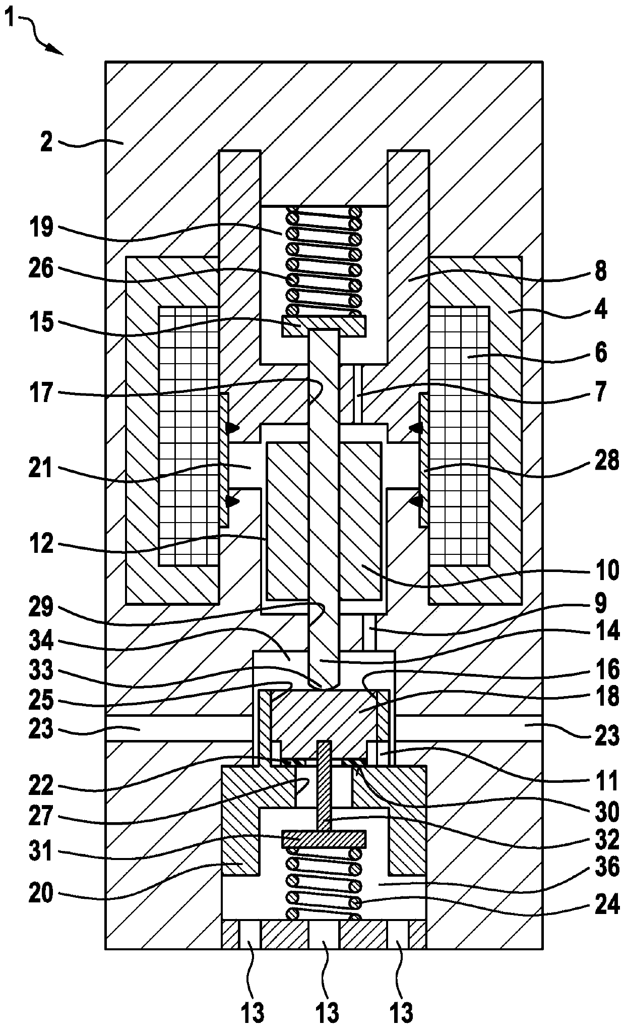
[0022] figure 1 A first exemplary embodiment of the proportional valve 1 according to the invention is shown in longitudinal section. The proportional valve 1 has a valve housing 2 in which an outer pole 4 , an inner pole 8 , a magnetic coil 6 and a nozzle body 20 are arranged. A first through-opening 17 is formed in the inner pole 8 , through which the first connecting element 14 protrudes, wherein the first connecting element 14 is axially guided in the first through-opening 17 . The first connecting element 14 is firmly connected to the solenoid armature 10 , wherein a magnetic air gap 12 is formed between the solenoid armature 10 and the valve housing 2 .

[0023] The inner pole 8 and the valve housing 2 delimit a spring chamber 19 in which the first spring 26 is arranged. The first spring 26 is supported on the one hand on the valve housing 2 and on the other hand on the disk-shaped end 15 of the first connecting element 14 and acts on said disk-shaped end in the direct...


PUM


Abstract

The invention relates to a proportional valve (1) for controlling a gaseous medium, in particular hydrogen, comprising a valve housing (2), on which a nozzle body (20) is formed. A closing element (18) is arranged in the valve housing (2), wherein the closing element (18) releases or blocks at least one passage opening (27) formed on the nozzle body (20) on a valve seat (30) formed on the nozzle body (20). Moreover, the closing element (18) is movably guided in a reciprocating manner in an axial guide (16) in the nozzle body (20).

Description

technical field [0001] The invention relates to a proportional valve for controlling a gaseous medium, in particular hydrogen, for example in a vehicle with a fuel cell drive. Background technique [0002] In the field of vehicle development, gaseous fuels, especially hydrogen, are an alternative to conventional liquid fuels. In this case, the hydrogen flow must be controlled in vehicles with a fuel cell as the drive, wherein the gas flow is not controlled intermittently, as in the case of liquid fuel injection, but for example using proportional valves which depend on the desired drive power Match the opening cross-section. [0003] DE 10 2012 204 565 A1 describes a proportional valve for controlling a gaseous medium, in particular hydrogen, wherein the proportional valve comprises a nozzle body, a closing element and an elastic sealing element. At least one throughflow opening is formed in the nozzle body, which can be released or closed by a closing element on the valve...

Claims


Application Information

Patent Timeline
IPC IPC(8): F16K1/36F16K1/42F16K31/06
CPCF16K1/36F16K1/42F16K31/0655H01M8/04089Y02E60/50
Inventor H-C·马格尔
Owner ROBERT BOSCH GMBH
Why Eureka
Try Eureka