
Wire restraining device for electric motor cycle

A technology for electric vehicles and wire harnesses, which is applied in the directions of attachment support devices, bicycle accessories, transportation and packaging, etc., and can solve problems such as affecting the appearance, potential safety hazards of electric vehicles, and foreign objects scratching

Inactive Publication Date: 2020-02-14
徐州康博智能控制仪表有限公司
View PDF11 Cites 0 Cited by
  • Summary
  • Abstract
  • Description
  • Claims
  • Application Information

AI Technical Summary

Problems solved by technology

[0002] There are a large number of wire harnesses in the front of the electric vehicle, including brake wires, power display wires, and handle wires. These wire harnesses are scattered in the front of the faucet. If the wire harnesses are not effectively wired, it will not only affect the overall appearance , and it is not easy to identify during the maintenance process. Moreover, the scattered wiring harness is easy to scratch with foreign objects, which may easily cause safety hazards during the driving of electric vehicles.

Method used


Image

  • Wire restraining device for electric motor cycle

Examples


Embodiment Construction

[0013] The present invention will be further described below in conjunction with accompanying drawing.

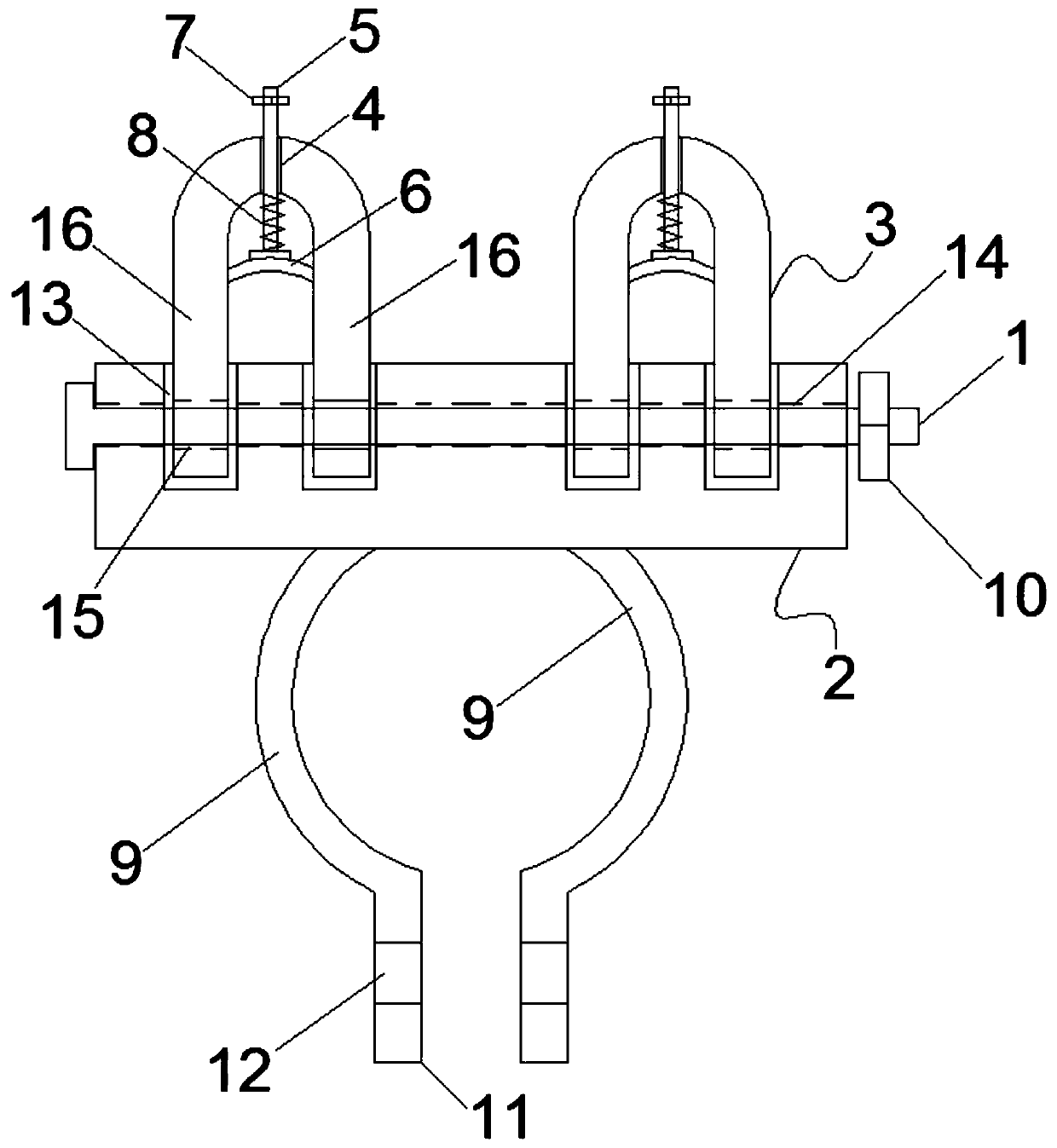
[0014] Such as figure 1 As shown, a wire harness device for an electric vehicle includes a wire harness mechanism, a hoop and a screw B1, and the wire harness mechanism includes a base body 2 and a plug-in body 3;

[0015] The insertion body 3 is U-shaped as a whole, and the center of the closed end is provided with a through hole 4, and a screw A5 is slidably pierced through the through hole 4, and the lower end of the screw A5 is fixedly connected with a sliding hole with the inner cavity of the insertion body 3. The matching pressure plate 6 and the upper end of the screw A5 are fixedly connected with a lock nut A7 which is limitedly matched with the closed end of the insertion body 3; the screw A5 is also provided with a reset spring 8 between the pressure plate 6 and the closed end of the insertion body 3;

[0016] The hoop is composed of a pair of arc-shaped clamping...


PUM


Abstract

The invention relates to a wire restraining device for an electric motor cycle. A whole connector body is in a U shape, a through hole is formed in the center of a closed end of the connector body, ascrew rod A is arranged in the through hole in a penetrating manner, a pressing plate which is in sliding fit with an inner cavity of the connector body is fixedly connected with the lower end of thescrew rod A, a return spring is arranged on the screw rod A in a sleeving mode, the upper end of the screw rod A is fixedly connected with a locking nut A, and a clamping hoop consists of a pair of arc-shaped clamping arms which are oppositely arranged; and two insertion holes which correspond to two extension arms of the connector body are longitudinally formed in a base body, a through-hole which penetrates through the insertion holes is formed in the transverse direction, positioning holes, corresponding to the through-hole, are formed in the lower ends of the two extension arms of the connector body, a screw rod B penetrates into the through-hole from one end of the base body and penetrates out of the other end of the base body after penetrating through each positioning hole in sequence, and then the screw rod B is connected with a locking nut B. The device can effectively restrain a scattered wire harness, can facilitate identification during maintenance, and can ensure the safetyin the running process of the electric motor cycle.

Description

technical field [0001] The invention relates to an electric vehicle accessory, in particular to a wire harness device for an electric vehicle. Background technique [0002] There are a large number of wire harnesses in the front of the electric vehicle, including brake wires, power display wires, and handle wires. These wire harnesses are scattered in the front of the faucet. If the wire harnesses are not effectively wired, it will not only affect the overall appearance , and it is not easy to identify during the maintenance process. Moreover, the scattered wiring harness is easy to scratch with foreign objects, which may easily cause safety hazards during the driving of the electric vehicle. Contents of the invention [0003] Aiming at the above-mentioned problems in the prior art, the present invention provides a wire harness device for an electric vehicle, which can effectively bind scattered wire harnesses, facilitate identification during maintenance, and ensure the s...

Claims


Application Information

Patent Timeline
Patent Type & Authority Applications(China)
IPC IPC(8): B62J11/13B62J11/19B62J11/20
CPCB62J99/00
Inventor 马金良
Owner 徐州康博智能控制仪表有限公司
Learn More