
Anti-scour device for offshore wind power generation

An anti-scouring and protection block technology, which is applied in the installation/supporting configuration of wind power generators, wind power generation, wind power engines, etc., can solve problems such as poor anti-scouring effect, reduced service life, poor buffering effect of anti-scouring devices, etc., to improve The effect of stabilizing performance, improving service life and improving protection effect

Inactive Publication Date: 2020-02-14
韦玉健
View PDF8 Cites 1 Cited by
  • Summary
  • Abstract
  • Description
  • Claims
  • Application Information

AI Technical Summary

Problems solved by technology

[0004] Aiming at the deficiencies of the prior art, the present invention provides an anti-scouring device for offshore wind power generation, which solves the problem that the buffering effect of the current anti-scouring device is poor, and part of the impact force of seawater cannot be removed, resulting in a reduction in the service life of the device , the anti-scouring effect is poor, which affects the practical effect of the device, and the protection effect for the wind power generation pillar is poor, making the wind power generation pillar vulnerable to seawater erosion, and the anti-scouring device reduces the stability of the wind power generation pillar during use.

Method used


Image

  • Anti-scour device for offshore wind power generation
  • Anti-scour device for offshore wind power generation
  • Anti-scour device for offshore wind power generation

Examples


Embodiment Construction

[0026] The following will clearly and completely describe the technical solutions in the embodiments of the present invention with reference to the accompanying drawings in the embodiments of the present invention. Obviously, the described embodiments are only some, not all, embodiments of the present invention. Based on the embodiments of the present invention, all other embodiments obtained by persons of ordinary skill in the art without making creative efforts belong to the protection scope of the present invention.

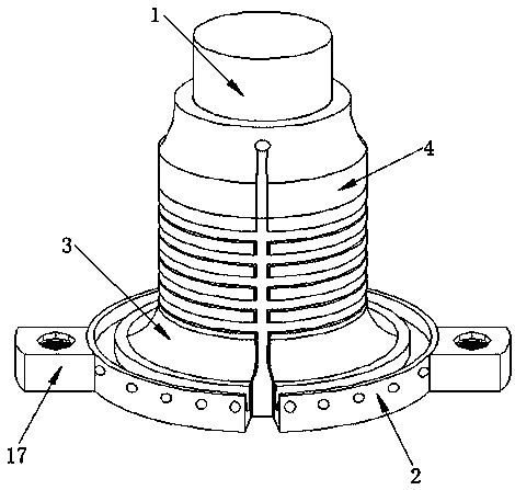
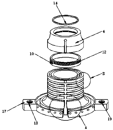
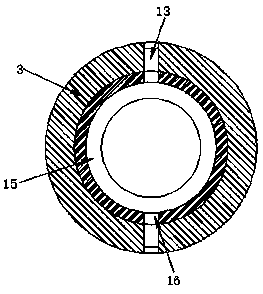
[0027] see Figure 1-6, the present invention provides a technical solution: an anti-scouring device for offshore wind power generation, including a pillar 1, a base 2, a protection block 3 and a connecting block 4, both sides of the base 2 are fixedly connected with a fixed block 17, and both sides The inside of each fixed block 17 is provided with groove 18, and the bottom of groove 18 inwalls is provided with screw groove 19, and the inside of protection bl...


PUM


Abstract

The invention discloses an anti-scour device for offshore wind power generation. The anti-scour device for offshore wind power generation comprises a supporting column, a base, a protecting block anda connecting block. The top of the base is fixedly connected to the bottom of the protecting block, the top of the protecting block is fixedly connected to the bottom of the connecting block through aconnecting part, and the inner parts of the protecting block and the connecting block are in contact with the surface of the supporting column. The invention relates to the technical field of offshore wind power generation. According to the anti-scour device for offshore wind power generation, as first annular grooves are formed in two sides of the surface of the protecting block and the sides, close to the protecting block, at the bottoms of the inner walls of the first annular grooves are higher than the sides, far away from the protecting block, a part of impact force of sea water can be relieved effectively when seawater scours the device by matching the first annular grooves formed in the protecting block with a second guide trough, so that the buffer effect of the device to sea water is improved. Meanwhile, sea water can be guided to flow out timely, so that the anti-scour effect and the practical effect of the device are improved.

Description

technical field [0001] The invention relates to the technical field of offshore wind power generation, in particular to an anti-scouring device for offshore wind power generation. Background technique [0002] Wind power generation refers to converting the kinetic energy of the wind into electrical energy, converting the kinetic energy of the wind into mechanical kinetic energy, and then converting the mechanical energy into electrical kinetic energy. This is wind power generation. The speed machine increases the speed of rotation to drive the generator to generate electricity. According to the current windmill technology, it can start to generate electricity at a breeze speed of about three meters per second, that is, the degree of breeze. Wind power generation is becoming a boom in the world, because Wind power generation does not require the use of fuel, nor does it produce radiation or air pollution. The devices required for wind power generation are called wind power ge...

Claims


Application Information

Patent Timeline
IPC IPC(8): F03D13/25F03D80/00
CPCF03D13/22F03D13/25F03D80/00Y02E10/72Y02E10/727
Inventor 韦玉健
Owner 韦玉健
Learn More